Archive for DC Car

The Worst RC Car in the World

Quite some time ago now, I wanted to make some of remote control car. And, also, eventually turn it into an autonomous sumobot or similar.

This project was done a few years ago, but I’m writing it up now.

In the interest of getting something into my hands that I can iterate on, I did it as quickly as possible.

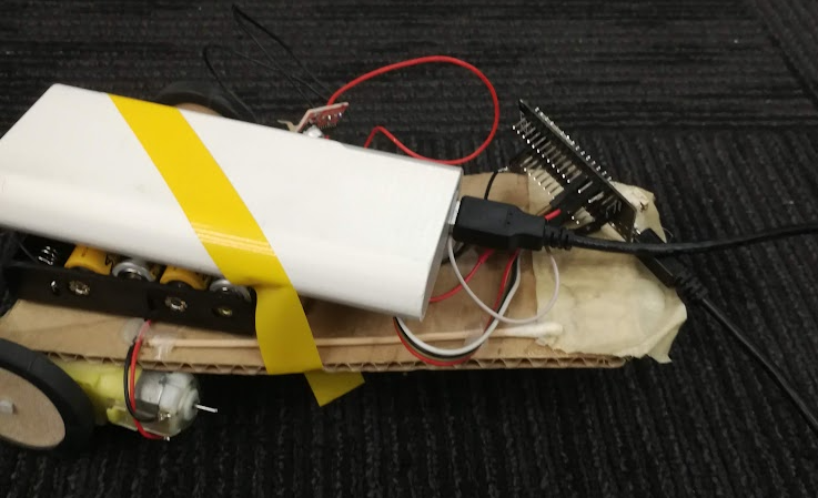
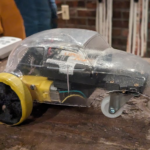
Yes, that is a structural q-tip. The cardboard was collapsing.

This crappiness is actually a feature – because I introduced this as a workshop to a bunch of people. Mostly beginners, with minimal exposure to electronics or microcontrollers.

Operation is simple. You program it in with your WiFi credentials, then when you turn it on, it creates a webpage that is just a joystick. That controls the car. It’s surprisingly satisfying.

The repo is here. It includes materials and code.

Everything in this sort of direction in the future will be a little bit more complicated or interesting, I just wanted to break the seal.

The fun in this project is quickly and cheaply building something simple, that can be controlled easily. No part of this is too hard to understand, and therefore, improve.

So with that in mind, I ran a few workshops to get other people started.

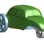
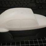
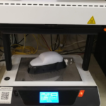
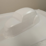
As a fun detour, I took the opportunity to play around with a vacuformer.

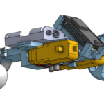
I modified a VW beetle model to remove the front fenders to better fit the single castor front wheel, then 3D printed the buck.

This is in parallel with designing an internal frame to hold all of the components together. For personal stuff, I usually use OnShape for my CAD, lately. The free version forces designs to be open source / publicly searchable, which is pretty great when banging together AliExpress modules. And also for the base VW model to modify into a tricycle.

Vroooom

There isn’t really any story behind this.


I have a joystick module, and it would be pretty simple to hook it up to a motor and use it for a remote control car.


I decided on a few parameters:

  • No microcontroller. Where’s the challenge in that?
  • Joystick wired directly to the car. Wireless can be a stretch goal, this is supposed to be a really quick project.
  • Front/back on the stick will drive 12v DC motors with variable duty cycle PWM for speed control while keeping torque high

This is a reasonably complicated analog circuit, and I really do prefer to simulate my numbers when I do that, just to make sure that I have a valid starting point for real-world tweaking.

I’m not really that keen on diving into SPICE (especially LTspice, which would be my only option, at the moment), but a cursory Internetting around came up with CircuitLab. Now, I’m not normally one to plug some commercial service without very good reason, but this service is seriously pretty great. It’s an online, cloud-based schematic editor and simulator.

I’ve been playing off and on with online services for five or six years, but really nothing has been any good.  But this one is really intuitive, free for non-commercial use, and they don’t even nag me about buying anything, even after detecting that I have an adblocker.


But anyway. I may or may not build this, it was mostly an op-amp and 555-hysteresis exercise.

Here’s the first stage, with a potentiometer(R5) controlling the op-amp output voltage. Varying the voltage adjusts the control voltage that the capacitor is allowed to charge to, causing the output duty cycle to change.

DC Motor - Single stage


Here’s a steady-state simulation of R5 low, PWM output (and therefore DC motor speed) low:

DC Motor Transient Low

R5 high, PWM output high:

DC Motor Transient High


Perfect.


That’s only half the battle, though. I need to get two inverted PWM signals coming off a single potentiometer, centred around the middle.

Part of the challenge of that is that you can’t just duplicated the above circuit. When the pot is involved with both high side(for controlling forward) and low side(for backwards), the circuits are somewhat in parallel.

Some small resistors to ground where needed to mitigate that. Eventually, I got a gorgeous graph that looks like this:

DC Motor Sweep

The important takeaway here is that the output voltage at the joystick-centred position is effectively nil for both sides. Each one respectively ramps up when the potentiometer is shifted to their side.

The 555 output stages aren’t in this simulation because they don’t change from the first circuit.

Here’s the second circuit:

DC Motor Full Schematic


The low-side 555 circuit isn’t shown either because again, doesn’t change.

A couple more notes:

  • I’d actually be driving this circuit with 12v, but capacitor charging rates are all relative, so the timing wouldn’t change.
  • Those two resistors to Vcc and GND, R6 and R9 are to adjust the joystick trim.
  • CircuitLab actually has excellent export options, too. I didn’t use them because I like the gridlines.


Again, this project is mostly just a fun simulation exercise. If I’m ever really hard-up for something to build, I’ve got everything written down here so I can do it. That may never happen, though.