Hysterical

After building my Piccolo and playing around, I really don’t like the software. It’s certainly simple and hackable and does a lot of what I need to do, but something about the Arduino/Processing pair don’t quite work for me.

Fortunately it’s just a bunch of servo motors, and I already have the PIC code in my toolbox.

Using my Arduino-form-factor PIC dev board and my Bus Pirate as a computer-UART bridge, I wrote in a simple protocol to communicate.

The “communication enable” pin will go high, and then two (might change to three) bytes get sent. The first is an “address” or command, and the second (or second two) bytes are a value/argument.

The 0 address is X axis, 1 is Y, and 2 is Z. The Z only uses binary 1 and 0 for arguments.

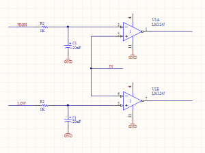
The z axi has two states: active and inactive. Inactive/up is the parked position, obviously. The active mode has a hysteresis loop attempting to control the position. The feedback is wired up to a window comparator, like so:

On the computer side, I’m controlling the Bus Pirate with a Python script that feeds it one scalar for a given axis at a time.

The speed at which the PIC executes the movement is controlled in the processor, to be tweaked. I will probably add that command in, when it becomes cumbersome.

As more commands become necessary, I’ll be adding more to the processor, I guess. Maybe eventually I’ll implement a rudimentary G-Code.


Now for the fun part:


Part of my original design goal was to have a 10ns response time. That’s very fast. Most of the old monolithic MOSFETs I’m using (because they’re cheap) have turn-on times in the tens of microseconds.

That totally blows my requirements out of the window, but there are still some optimizations to be made. By using analog circuitry, I can directly control certain parameters and speed them up, compared to hitting a microcontroller and being a slave to a clock source and interrupts getting in the way.

I’ve designed a window comparator. It looks like this:

Window Comparator

If the input goes above the “HIGH” voltage, then the top output turns on. If it goes below the “LOW” level, then the bottom output turns on. There will be two of these circuits. Feeding these outputs to some discrete logic, or something clever that I haven’t thought of yet, I can turn on or off transistors to the different power stages.

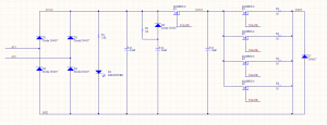
EDM Schematic V2

There are three power stages: Stage 1 (rectified input), stage 2(charge), and stage 3 (output).


The S2 MOSFETS can be ignored, just treat them as one. I should be able to parallel as many as I need, within reason, it doesn’t change (most of) the math.


The input of one window comparator is from VOUT, and the outputs are hooked up to the micro. If the HIGH output is on, then that means the MOSFET Q2 is on, but the EDM electrode has not made contact with the workpiece. Start (or continue) jogging the Z axis down.

If the LOW output is active, then we’ve gone down too low, start jogging up.

The other comparator’s input is at S2VCC. That controls the turn-on and turn-offs of the MOSFETS. If C3 is too low, then Q2 must be shut off and Q1 turned on to charge it up. When it is high, flip that. The idea is that Q1 and Q2 should never be on at the same time, providing a direct path to ground. The logic here will also involve halting the Z jogging, or making it jog up.


So there you go. With two different kinds of hysteresis going on at once, there will be some experimentation going on with how they work together. That leads me to one last trick:

You see the HIGH and LOW inputs on the comparator circuit? Those must be an analog voltage. That I’m going to set with a PWM out on the micro and the caps smoothing it out to an analog value. Varying the duty cycle of the PWM will allow me to vary the analog voltage.


Counting up my PWM outputs:

Two for each window comparator (4 total)

One for each axis (7 total)

One for the oil pump (8 total)


I haven’t discussed that last one yet, but stay tuned!


Altoids tin Pickit

Pickit is the officially supported programmer for Microchip’s PIC line of microcontrollers. The newest revision, Pickit 3, supports the latest and greatest micros, but does away with some fun stuff like in circuit debugging.

Fortunately, when Microchip dropped support of the Pickit 2, they open sourced the schematic so there are tons of clones out there that have all sorts of different features or design considerations.

There are through hole versions, dead-bug versions, versions built with components on hand, and versions built to original standards.


I’ll be using this Pickit 2 clone schematic:

http://diyfan.blogspot.ca/2013/06/original-pickit-2.html


I like this one because the official schematic has storage space for programming-on-the-go, which adds a lot of complexity. I have literally never used that functionality on mine, so I’d rather save the weight. All of these components are also easily sourced on the grey market. I’ve checked. They’re cheap.


Most clones are through-hole because they’re done on proto boards, but surface mount components are important here for keeping it low-profile.


So I’ve redone it in Altium. I’ve add programming headers for the PIC itself and broken out all the spare pins, but otherwise kept it pretty close to the original schematic.

I’ve also decided to fit it in the gold standard of hacky enclosure styles: The Altoids tin.

It’s kind of surprising that I haven’t seen this done before.

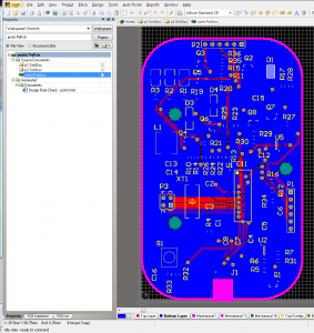
Using the Altoids tin dimensions provided by Adafruit, I’ve designed this PCB. The tin will require some cut-outs, but it looks pretty simple.

Here’s a teaser:

9


It’s two layers for cost, all components are on one side, and there are fiducial marks for a pick-n-place machine. Basically, I’m trying to make this manufacturable. I have no intention of doing so, but I did it because I could.

As usual for most of my projects lately, all files (including Gerbers) are here.

Note: The positive rail for the op amp is not connected to the VCC net. Whoops! Blue wire or respin required, if I ever come back to this.

Using Altium for a DirtyPCBs order

This is a pretty rare combo: using a premium PCB package with the budget board house.


Kinda funny.


Generally these small run PCB houses provide DRU and CAM files for EAGLE design rule checking and Gerber outputs, respectively. Because I’m using Altium, I had to make it up as I went along.


It gets much easier when you understand what Gerber files are. While we’re all used to standard, unified output formats that contain all of the data we need, Gerbers are very much still a holdover from manufacturing in the 80s.


When you export these, a whole bunch of files get generated. This is intimidating, but don’t panic! They all have different extensions like GBO, GTL, etc. These are all the same type of file.

As I’ve said, while you’re used to unique file extensions being different formats, these are a holdover from 80s manufacturing and the PCB industry still hasn’t caught up. That means that by changing file extensions, you can play around with different layers doing different things.


So here’s how you generate the appropriate Gerbers. I used a mostly the default rules for this, I’m not pushing the limits. Maybe next time I’ll generate the proper rule sets.

Read and understand these directions before you start. They require some forethought.


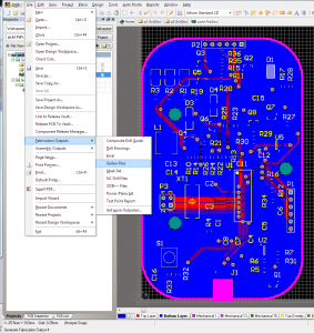
Start out with your finished PCB.

Capture


Do the thing.

1


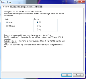
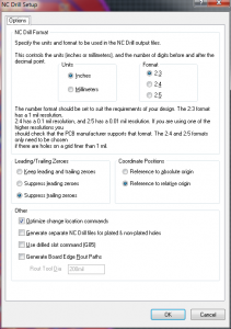
The resolution options matter here. There’s no way Dirty PCBs can handle the higher res, so turn it down a notch.

2


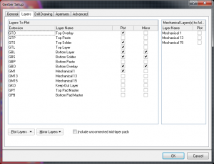
In the next tab, this is where you’ll have to do some thinking. Every project is slightly different. So for this one, I want the top overlay (silkscreen), top solder (gaps in solder mask for your pads), and top layer (copper). Same thing for bottom.

You also need a board outline. Older versions of Altium don’t have a dedicated “outline” layer, although I believe newer ones do.

So what I did was change the board outlines to Mechanical 1, and now I’m exporting that.

A couple more notes:

If I wanted to create a solder paste stencil, I would also export the Paste layers.

If you want through-hole slots, you will need an additional layer. This includes slots that allow you to panelize. Export them on another mechanical layer, and I’ll talk about it a little later. I’ve done this before, DirtyPCBs does a great job of this.

All of the other tabs in this dialog are kept at default values. Don’t mirror the bottom layers as shown. I did that and it was Wrong.

3

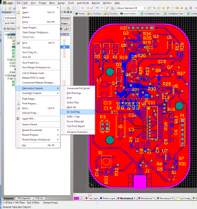
I lied a little bit above. Of the exported files, there is one that is not like the others. The drill file (.TXT in this case) requires it’s own export.

4

Do the resolution thing again, and everything else is default.

5

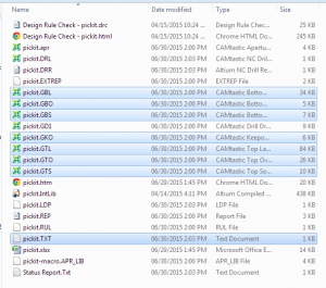
Okay! Now we’ve got all the files we need, let’s make sure they’re in the order they need. Here’s the key on the DirtyPCBs website.

As you can see, it’s super similar to what we have. The top 6 are exactly what we exported, and the drill TXT, too. The outline is the only thing that’s not quite right.

6

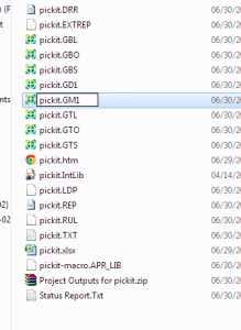
We exported it this time as mechanical layer 1. Easy fix, just rename the GM1 file to GKO. If you’re doing internal slots or self panelizing, you’ll also have exported another mechanical layer. Say, GM2 or GM15 or anything you like. Rename this to GML and include it with the others.

7

And there you go! Zip up all of these files, and they should turn out alright. GD1 is the Gerber drill file that this board house doesn’t use, just ignore it.

8

An important step: Check your files.

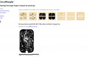
CircuitPeople is an excellent and simple online Gerber viewer. Look at all your layers and make sure nothing is terrible.


9


And you’re done! Send it off and enjoy your boards.

If something screws up in the order, I’d like to hear about it, but I take no credit. These steps have always worked for me, but this particular company probably won’t tell you if anything is wrong with the files. They’ll just manufacture it and send it on.


CNC Day

Aw yeah, CNC day.

CNCed Tank

Pretty simple parts, I guess it wasn’t strictly necessary to use a CNC, but hey, it was there.


Here it is coming together.

Tank Test Fit


A spaceship!

CNC Spaceship


~~~~

Brief interlude

~~~~~~


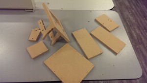
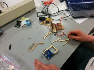
Laser cut Piccolo parts.


Piccolo Assembly


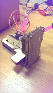
And the rest of it.

Piccolo Assembled

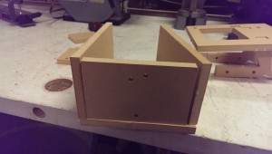
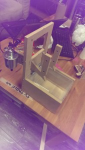
Rough-ish final box.

Small EDM Tank

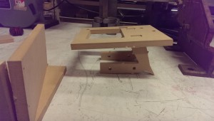
And it flips up!

EDM Tank Up


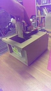
So the next step is to figure out a way to mount the Piccolo on top of the box as shown. There’s a little bit of MDF I need to cut away to make it fit better, too.


After that, I need to modify the Arduino sketch (ugh) to jog the Z-axis up and down to keep the electrode in the conductive region.

WPA2 HMAC SHA1 PMK FPGA VHDL

Hell yeah, acronyms.

Restartin’ dis.

I’ve got the old working SHA1 encryption algorithm going. It’s up on GitHub, here. I was waffling between parallel and serial loads and outputs. SHA1 takes a 512 bit input and outputs 160 bits, and no FPGA that I have access to will have that many pins.

Here’s a fallacy I got stuck on for a while:

If I use completely parallel I/O, it’s faster. Therefore, I should try to use as much parallel communication as possible to maximise speeds.


The truth is, though, that most modern high-speed circuits use serial data. When you’re clocking at very high frequencies, propagation errors become very difficult to mitigate. With many data lines, you have no way of knowing when exactly data arrives at the lines. It’s better, easier, more reliable to just send one bit at a time and pump them through really fast. That’s a core principle of pipelining; you don’t even need to wait for a signal to reach its destination before you’re sending the next one.


With this project, I don’t think I can go faster than 100MHz with the FPGAs I have. That’s right on the edge of where efficient pipelining starts to matter, so I’ll be experimenting with a mix of serial and parallel interfaces to see how far I can stretch it.


Right now at this moment, though, I want to get the computationally-intensive parts of the WPA2 protocol offloaded to the FPGA. I won’t worry about speed juuust yet.


Here’s how WPA2 works, from a security analysis perspective:


Some definitions


  • Access Point (AP) – Usually the router, in these systems
  • SSID – AP name. This is the router name that you connect to
  • Master Key (MK) – AP password. This is the key we ultimately want to find
  • Pairwise Master Key (PMK) – This is the cryptographically hard part of the whole transaction. It’s derived from the MK and SSID
  • Pairwise Transient Key (PTK) – The cleartext portion of the authentication to verify the correct PMK
  • PBKDF2 (wiki, RFC) – Password-Based Key Derivation Function 2 – A cryptographic function, used like PBKDF2(PRF, Password, Salt, c, dkLen) where PRF is any given hash function, c is the quantity of iterations, and dkLen is the output length
  • HMAC (RFC) – Hash-based message authentication code – Intermediate function applied to the SHA1 hash
  • SHA1 (RFC) – Standard hashing function. Uses a one-way algorithm to generate non-reversible output


The AP has the password, from which it can derive the Pairwise Master Key (PMK). To verify that both sides of the transaction have this, a PTK is generated using the PMK and nonces (randomly generated, one-time-use numbers).

This PTK is transmitted over cleartext, and is part of the 4-way handshake.


So, in short, if you combine the proper PMK with the proper PTK, the whole conversation breaks wide open and you can associate with the AP.

If you’re watching the WPA traffic, then you can easily capture the 4-way handshake and therefore the PTK.


That means that, for my purposes anyway, the PMK is the important unknown variable, and the computationally hard part. Here‘s how you calculate it, from top to bottom:

PBKDF2:

x1 = HMAC_SHA1(MK, SSID + "1");
x2 = HMAC_SHA1(MK, SSID + "2");
f1 = x1
f2 = x2
for(i = 1; i < 4096; i++) {
    x1 = HMAC_SHA1(MK, x1);
    x2 = HMAC_SHA1(MK, x2);
    f1 ^= x1
    f2 ^= x2
}
return f1 + f2;


HMAC:

This is more complicated. Given HMAC(secret, value)

  •  Initialise two 64-byte variables, Bi and Bo with secret, padded with zeros on the end
  • XOR each of byte of Bi with 0x36, and XOR each of byte of Bo with 0x5C
  • Append value to Bi
  • Append SHA1(Bi) (in Ascii!) to Bo
  • Return SHA1(Bo)

In short:

HMAC_SHA1(s, v) = SHA1((s ⊕ 0x5c)||SHA1((s ⊕ 0x36)||v))


And finally, with the SHA1 function, I have covered it in previous posts. This portion is already done.

Imbles of Gimbals

I got handed a box of old gimbals from a movie set! I love gimbals!


Most of them are very slightly broken in very repairable ways.


I left, like, 5 for other people to fight over, and grabbed two for myself. One of them was in great shape, the other had some loose set screws and was missing an encoder. Fortunately the bin had some spare encoders!


Anyway. I stashed the good one, and focused on the brokenish one. Fixed it up, and started wiring up some drivers.


Here’s what the gimbals are like:

On the horizontal axis, there’s a DC motor with a gear meshing with the base. On the other side of the base gear, there’s another one connected to an optical encoder. There is also a photo-interrupter at one point along the rotation for calibration, I guess.

So the base can rotate freely in either direction indefinitely.


There is a slip ring that passes some wiring up to the vertical assembly. A similar system is in place for that motor, with an encoder tracking absolute position, but this one only has about 45 degrees of travel. There is a limit switch at either end, and a bunch of spare lines to be used for a camera or whatever.


This system is extremely easy to reverse engineer. All of the cables are out in the open, only disappearing into a slipring, where the maintain colour code.


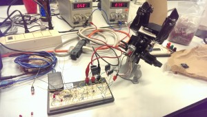
So I starting breadboarding a motor driver. The brain is an old PIC that was in a bin somewhere, and I tried to find some driving transistors that would work. I burned a couple, and then took stock of what components I had on hand.
There was really no transistors around that fit the bill. I measured these DC motors to run at a good speed at about 8.5v and 500mA,so the power requirements are not low, when you’re trying to use 3906 BJTs or whatever.

Breadboard H-Bridge


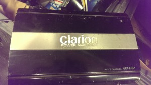
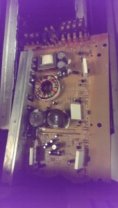
That day ended there. I thought about the problem for a few days, then I came back and grabbed a 200w amplifier from the recycling bin and pulled it apart.


300W Amp Outside300W Amp Inside


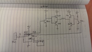
Inside it were 4 sets of 2SA1908 and 2SC5100 complementary BJTs. Perfect. Wired them up like so, and I have a gimbal driver.

Gimbal breadboard schematic

Now I need to incorporate all of the sensors.

First Burn

During my research on how others have handled the sparking circuit in an EDM, I’ve been fairly unimpressed. Off the top of my head, there was one 555-based pulsing EDM circuit, one purely analog circuit that was never built, and one hand modulated system attached to a drill press.

It’s hard to tell exactly what will make a winning design, so I’d rather not hamstring myself with fixed logic that may or may not be ideal. And for the first few iterations will almost certainly fall on the “not” side of that line.


What I’ve settled on (and indeed, what my education is in) is computer control. Small microcontrollers have gotten fast and cheap enough that there is very rarely a reason not to use them, other than bragging rights or very high volume manufacturing.


That’s a little bit unfortunate in some cases, but it’s great for this one.


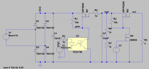
Here’s a first third draft of the circuit I’ll be using. I had a few false starts, but this one is the first one I actually (mostly) drew out, and it seems to work. I used two power supplies in series to get 60V and breadboarded it up. Not the final 80V supply, but close enough.

EDM SPICE

I only simulated the first stage (and with the wrong optocoupler!) but it proved the concept.


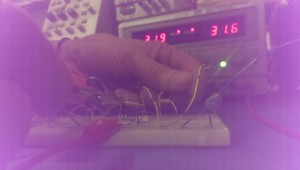
So I got my first burn last week to prove the concept! I tried to get a picture of the sparks, but it was tricky with my crappy phone camera. I was totally welding wires together, though, it was awesome. In theory, that shouldn’t even cause excess wear on my components or power supply. Everything is well within spec.

First Burn


I’m a little but worried about the speed of my components. I’d like to be able to get this pulsing in the 20ns range, but I’m pretty far away from that, I believe.

The two important components in this are the H11D3 optocouple and the IRF9540 P-Channel MOSFET.


According to the datasheet, the transistor has a rise time of 73ns, which right there blows my timing requirements. It has a turn-on delay of 16ns which also isn’t fantastic. That’s 100ns just for the transistor.


The optocoupler is worse, however. About 5 us. I’m not familiar enough with them to know if that’s a good value or not, but I’ll look at my options for rev 2.

Worth noting that this has a base connection, which doesn’t seem to make sense, given that the optical input is basically the base.

From here, though:

Click to access an3011.pdf

It looks like it’s to my advantage to use the base! It’s floating for now, but I’ll tweak the values to get to the most out of it when I have a scope on it.

Start small.

Other than wanting to spend very little money on this project, the scope of it is huge enough that I’ve been trying to use as many prebuilt components as possible.

If I have the majority of the project build with discrete, modular components, then I can start drilling down and replace the weakest links, one at a time.

Because the CNC portion is horribly complicated, and itself comprised of several parts (drive electronics, mechanical movements, control software, firmware), several weeks ago I made the decision to use a low-cost CNC platform. I mean “platform” in the sense that it’s designed as a starting point to hack, redesign, and improve.

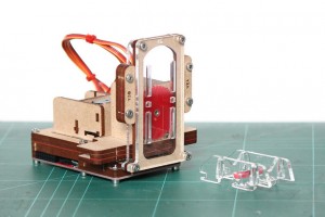
It’s called the Piccolo:

piccolo stock

It uses three (TINY!) servo motors, a bunch of laser cut gears and mounting plates, and some Processing-based software. Everything is open-source, and I don’t think they even sell any of the components themselves. They provide all of the files and expect people to make it on their own, which is kinda cool.

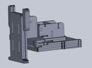
One thing I couldn’t find on their site anywhere was the work area. I needed dimensions of all of the parts to mount and design around this anyway, so a couple hours with their laser cutter files produced this:

piccolo model

Turns out all axis have a range of about 2.5 inches. That’s really tiny for a CNC platform, but definitely usable for making PCBs. At first, anyway. That double-ensures that this portion will eventually be replaced, probably with a CNC system of my own design. That will be fun, I am looking forward to it.

One note for future-self:

There is a decent chance that the sparking from my electrodes will cause enough interference to mess with my servos. If they get really jittery during a burn, I know exactly what is happening, and a redesign will happen sooner rather than later.

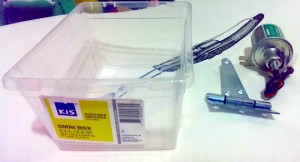
Working with the above files, I gathered together some more materials:

EDM Tank Supplies

A 12V oil pump($12) for the EDM fluid (more on this in a future post), a standard heavy duty door hinge($3), and a small plastic tank($0.89). The tank is a lot smaller in person than it looks.

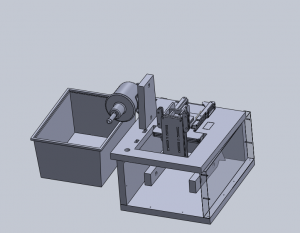
Putting it all together:

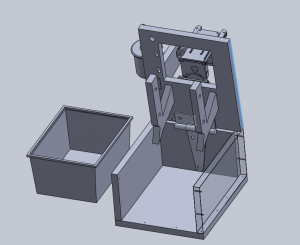
edm tank model 1

That’s a reasonably accurate mode of the tank on the left.

There’s also models of the Piccolo and the fuel pump that you can see there.

The rest of the frame is designed out of 1/2 inch MDF. The tank fits in the box, which can flip up like so:

edm tank model 2

And BAM. Hinges. The idea is that the whole mess can flip up for servicing, changing out the PCB, etc.

The PCB holders at the bottom might be changed a little before I build this, but the idea will stay the same. They’ll be submerged in the EDM fluid in the tank during operation. Afterwards, the top flips up, and those PCB holders are angled so that the oil drips back into the tank.

That should mitigate oil going everywhere somewhat. I still expect this to get messy.

FFChkMate

I’ve posted here before about my troubles with flexible flat connectors. Well, not directly, but that always seems to be a tangential obstacle in the already perilous minefield of hardware hacking.
Basically, I hate them and I want them to go away.

The answer is, obviously, a breakout board, but I was having trouble finding exactly what I wanted. The system that I was having trouble with is 0.14mm pitch, and an odd number of pins. That means that the connector’s pins are staggered instead of directly across from one another. Slightly unusual, and I couldn’t find an inexpensive breakout board for it.

Over an evening, I started designing a board that should help. The idea is to keep a few of these boards on hand, and if you’re working with an FFC cable with a pitch of 0.14mm, toss an extra cable and a couple connectors onto your next Digikey order. Should run you a couple bucks.

In choosing what kind of connectors I wanted the board to support, I had some decisions to make. Odd or even pins? How many?

I solved those by parsing Digikey’s catalogue:

FFC Chart


A general theory is that the more connectors of a certain pin count in the catalogue, the more common it is in the wild. As shown, it’s definitely important to support more than 30 pins. There’s another big spike at each common count, ending at about 51. That settled that.

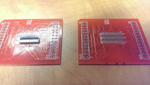
There was another clever idea involved: the centre of the board is a flat cable connector footprint, with a little bit of a tweak. The middle row of pads correspond to pin 1, and every second pin after that. Depending on whether your connector has an even or odd pin count, you use the outer row of pads that are in-line or staggered, respectively. Those all break out to the pin headers as shown on the silkscreen.
There’s your breakout. If you need your cables connected to the device under test, use two boards, solder female header pins on one, male on the other, and sandwich them together, both connectors on either the inside or the outside as shown.

Obviously this may cause issues with length-matched traces, but you know. Cross your fingers. Worth a shot.

Future goals: Actually draw the traces myself, because the autorouter is terrible. I just wanted to spend as little time on this as possible.


FFChkMate


It seems to work fine, though. I’m not trying to get GHz signal through it or anything.


You can get one through dirtypcbs here, or I’ll release the files when I eventually dig them out and make the traces pretty.

Travel-PIC

With the huge popularity of Arduino in the past few years, everything that can be advertised “Arduino-compatible” is being commoditized to such a huge degree that it can be hard to find price-competitive components that do not have that distinctive Arduino pin layout.


An example is this TFT touchscreen LCD. It’s like, 6 bucks, which is insane. This is definitely going to show up in some future projects of mine.


Having everything work as an Arduino shield is all well and great, but I’m generally against using them. My problem with that whole ecosystem has always been that:

A) It shields(get it?) you from what is really happening on the microcontroller

B) It follows that if the user is unfamiliar with the inner workings of their system, then they will be motivated to leave the entire Arduino in place in their project

Historically, that second point has meant that people will build a project and run it permanently using what amounts to a single $30 microcontroller.

With the above commoditization argument, this point is fast losing ground when you can now buy a Chinese Arduino clone for $3.


Those arguments don’t even make sense anymore! I guess what it boils down to now is that Arduino offends my inner perfectionist.

Microchip PICs are fantastic because they are easy to use, powerful, and extremely inexpensive.

I can find a 60 cent chip that has exactly the peripherals I need, with almost no bloat.

The problem is that I have to build it into a circuit every time, thus negating the cost benefits with a time penalty.


Anyway. I have a whole bunch of PIC18F4520 DIP packages kicking around, and some other similar ones (4431 I think?). I suspect that I will be forced to start using Arduino eventually, but at least with this method I can now do some of my simpler PIC development on-the-go with USB power.

For some reason the TSA doesn’t like it when I try and take a breadboard, wire, and wire strippers onto a plane.

So the result:

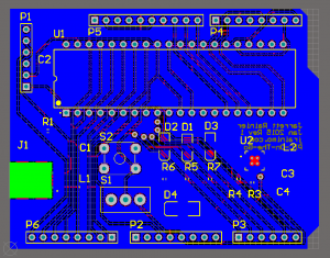
A PIC dev board in an Arduino form factor.

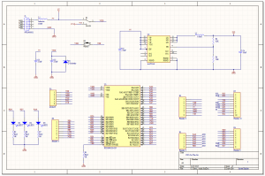
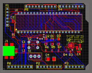
PIC-On-The-Go SchematicPIC-On-The-Go Bare BoardPIC-On-The-Go with fill


Powered by USB (no communication, though), switch-selectable 5V/3.3V power rail (don’t hit this while plugged in!), reset button, 3 LEDs, and I’ve tried to match most of the Arduino pins with the associated PIC functions (eg. SPI and analog pins are in the same location).

You still need an external programmer, but that’s okay. Programmers are pretty cheap and come in a sleek form factor. The programming header pins match the Pickit 3’s pinout, so it’s just plug-and-play with MPLAB.


When I get the board and give it a test ride, I’ll release the source files. Altium, though, so many people won’t be able to edit them.