Archive for Lamp

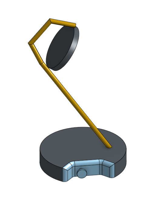
Brass Lamp

I haven’t properly built anything with my hands in a while, so it’s time.


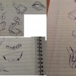
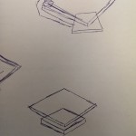
I mocked up a few lamp ideas, and this one seemed fun. Really, really rough mock-ups.


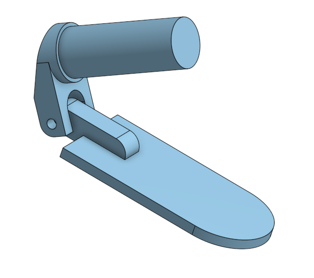
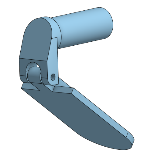
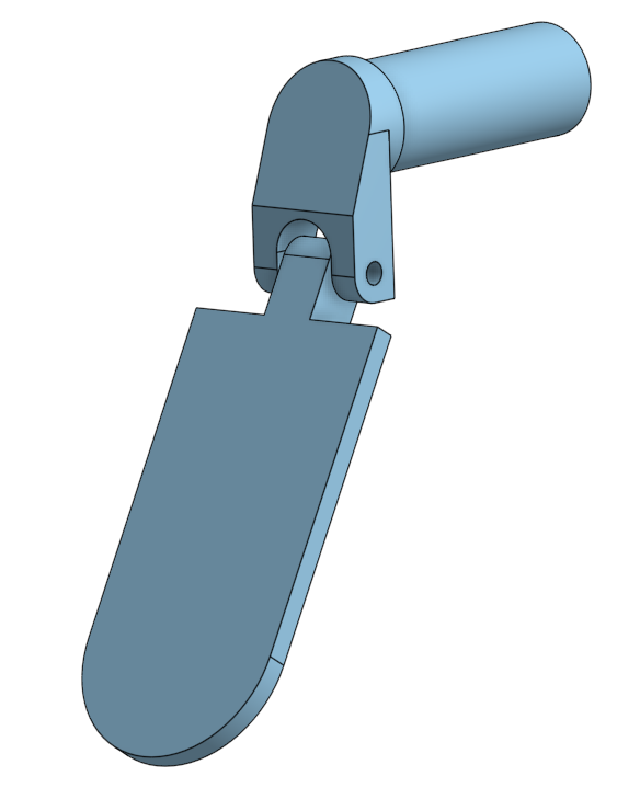
That was neat looking, so I fleshed out the hinge section, which I expected would be the hardest part to figure out and build.


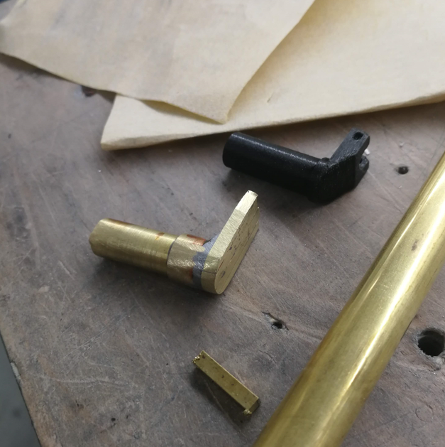
First, I 3D printed the hinge, just to get a feel for if my sizes felt right – I am bad at judging size in CAD, things often turn out way larger or way smaller than I expect, and therefore really difficult to build.
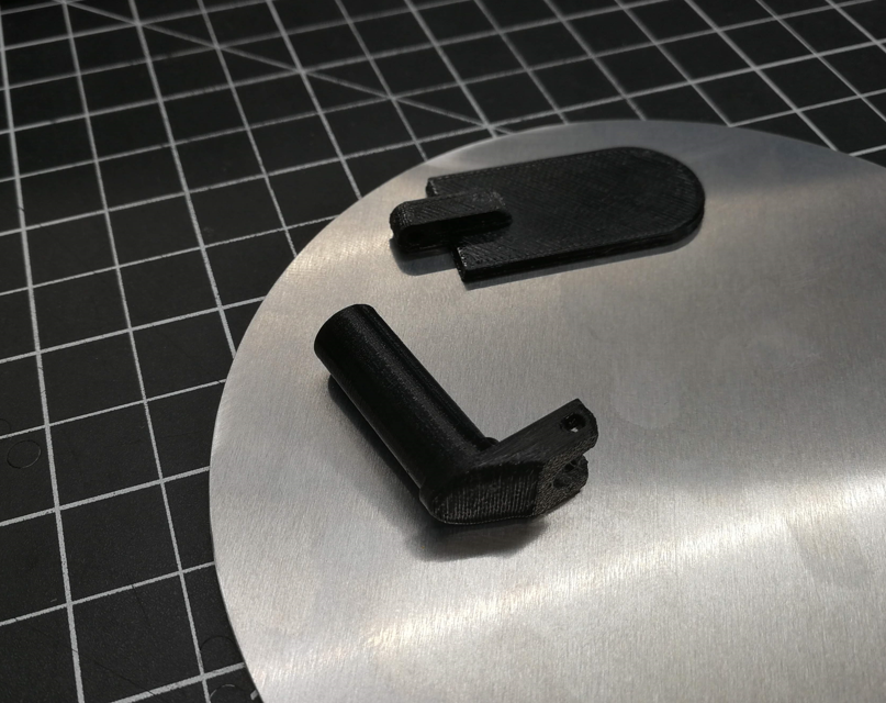
 

These looked fine, though.


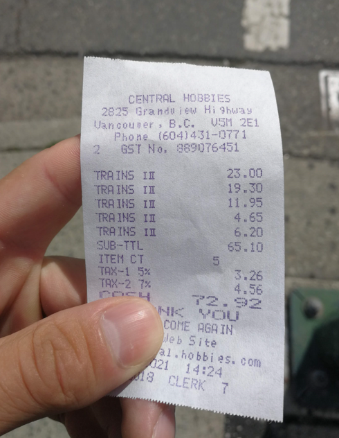
I picked up a ton of brass from a hobby shop. Can you guess what the main focus of the hobby shop is?


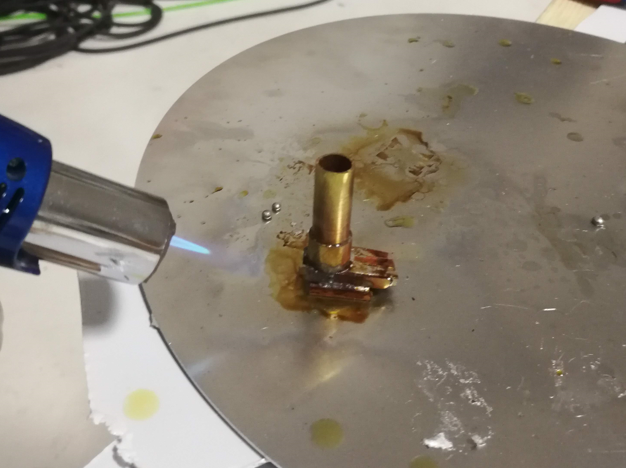
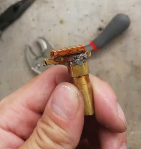
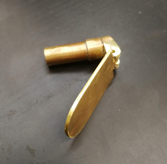
For the hinge pieces, I didn’t have the right shapes or size of brass stock available, so I needed to cut a bunch of smaller pieces and then braze them together with silver solder. And then took them to the belt grinder.


Pretty close!


And then tried to add one more piece, dropped it while the solder was molten, and had them splatter apart on the ground.
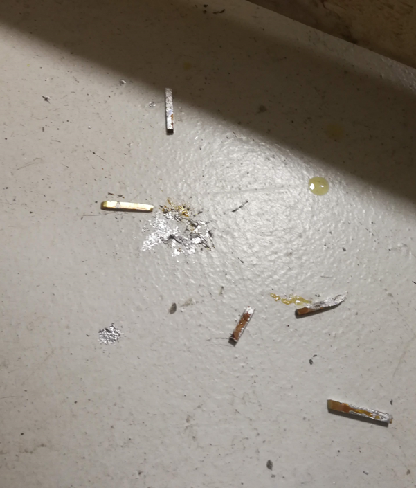


Okay one more time.


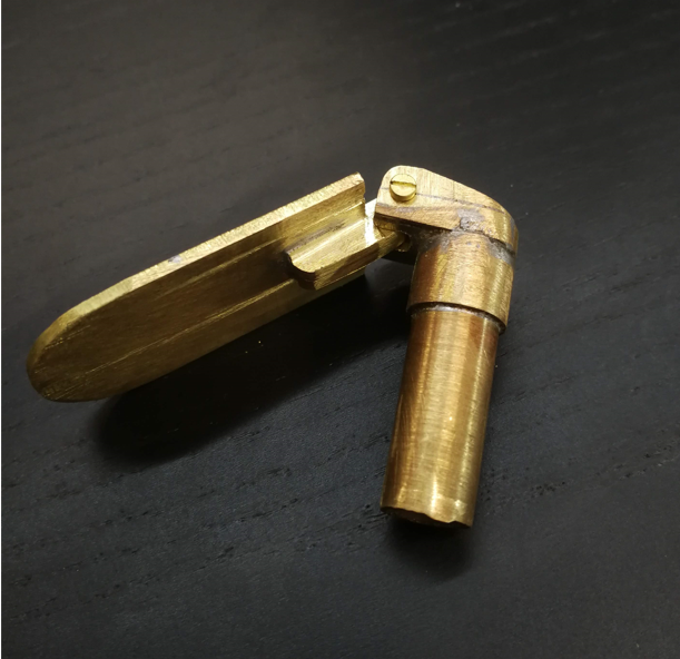
It’s always better the second time, anyway. I used an M1.5 brass screw as the hinge pin.


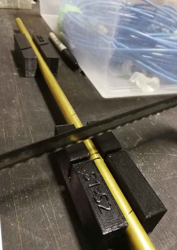
For the stand, I 3D printed some saw guides so that I could get the tube angles perfect. The stand wouldn’t end up with the right geometry unless the cut angles were just right.
 

Then, after brazing:
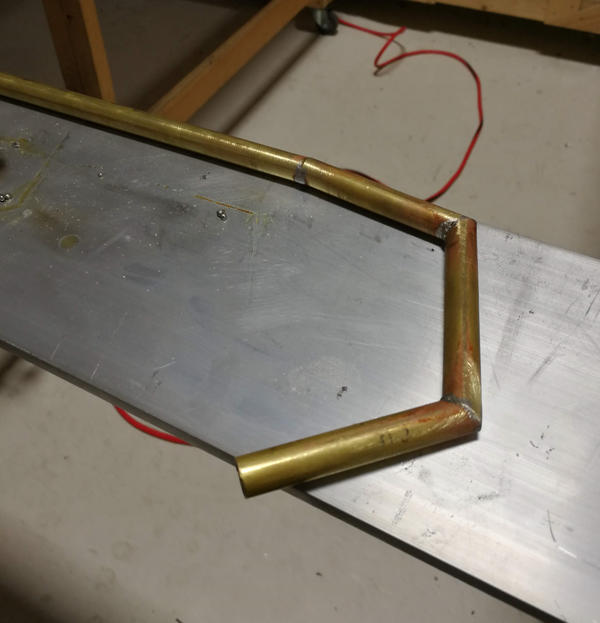


It matches up with my CAD perfectly, I’m stoked.


Some blu-tak was used to hold the hinge pieces and light backing together to get a sense of how it was all going to go together.
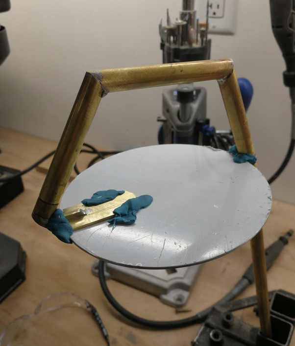


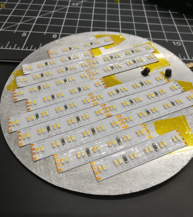
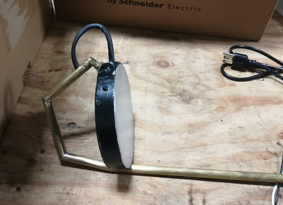
The light panel itself was a circle of aluminum that I spraypainted black. Then I riveted the hinge on and laid out my LED tape.


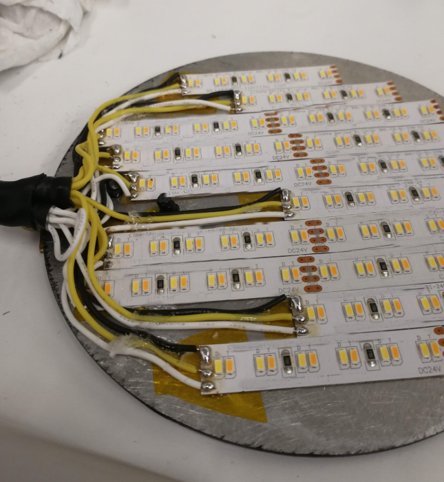
Wiring.

This could have been done much neater. Next time.

Encircling the LED panel, I bent some flat bar aluminum, riveted it, glued it, and painted it. Then glued on a plastic diffusion circle. This was all done quickly, so I didn’t take many pictures.
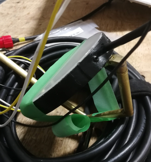
 

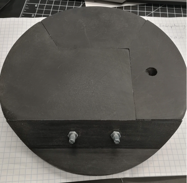
For the base, some nice dark wood would be ideal, but that would have required a fair amount of material acquisition and hunting down tools I wasn’t up for, for this project. So I took my base, and split it up into easily printable chunks.

I was going to attach them together, sand, patch, sand, and paint them to turn them back into one object, but I kinda liked the jigsaw effect, so I left it. PETG sands really well, and I treated it with a light oil coating to keep it from taking on fingerprints.

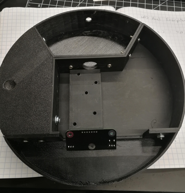
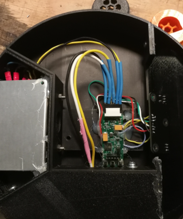
The pieces are just bolted together, and mostly hollow to allow mounting of the electronics.

For the controller, I have a surplus prototype lighting controller of dubious origin, and wrote some firmware to handle fading and mixing the two LED channels. The 24V power supply comes from AliExpress.
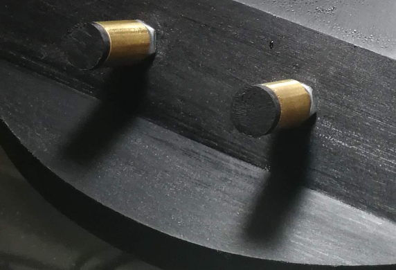
Similarly, for the knobs, I went for an easy and quick solution using 3D printing for the ends to retain a little bit of the brass tube onto the potentiometers. The left knob controls the light intensity, and the right knob controls the light’s colour temperature. This lamp can fade in between a really cool white and a really warm light.
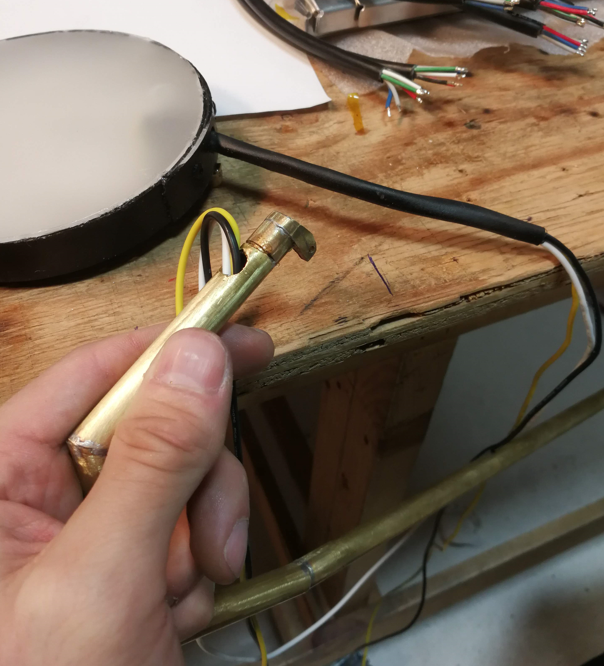
Running the wires through the brass tube was a fun adventure. What I ended up doing was fill the tube up with oil, run a single wire up through the bottom, then solder it onto the other three wires. After that, I could use the first wire to pull the whole mess back through the tube. Then I flushed the tube with alcohol to clean it all out.

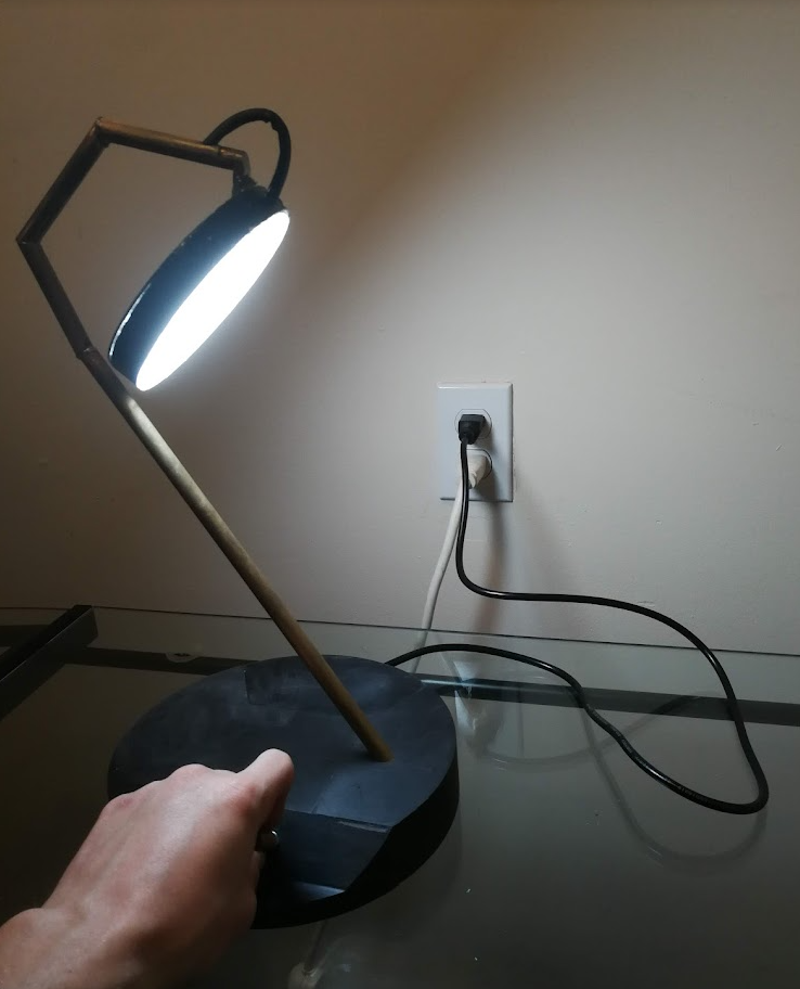
And, final wiring, and it works! It looks great. I can see all the small defects, but that’s okay. I’ll do better on the next one.
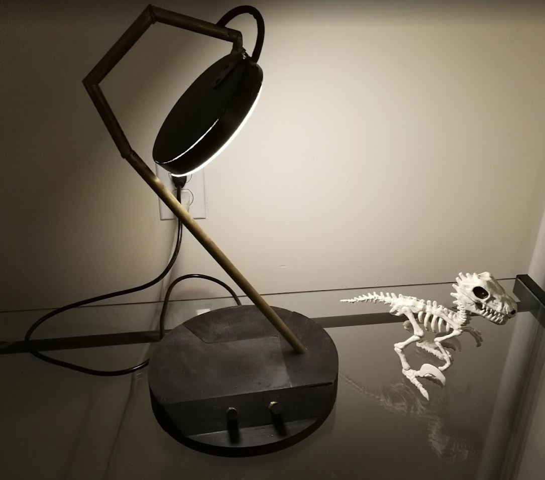
I don’t lamp well


That was a long “next month”. A recap is in order. This post chronicles the long descent into complete and utter apathy.


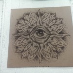
In September 2014, I made some sketches for a lamp I wanted to build. The intent was to use the glass plate from a desktop scanner as the light diffuser, and laser etch a fractal pattern onto it to create a frosted effect, instead of being optically clear.

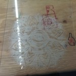
Here is a test piece I did, with a laser cutter and an image found off the internet.


The results were pretty fantastic. Fine details get lost, because it looks like the mode of operation is the laser heating up enough of the glass to chip off a small chunk before moving on. And so on, for the entire image. It creates great looking, even optical diffusion, though.


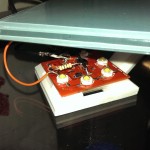
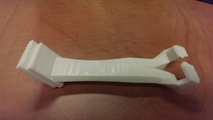
For another test, I decided to design and build a similar, but smaller lamp. Glass scanner beds are a limited supply. Using a glass tile I found at a craft store, I designed an arm to hold it onto a wall, a few centimetres away from a PCB containing some high power LEDs.


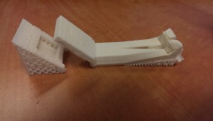
The initial model and 3D print is shown on my previous post.

Here is the final version, with some corrected measurements and better mounting point.

Lamp print


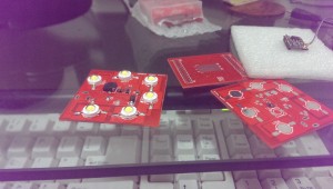
And the PCB arrived shortly after the last post.


Lamp PCB

Oops!

That’s mistake number one. Everything was intended to be clean and white, but I guess I forgot to change the soldermask from the default DirtyPCBs red. It’s not the end of the world. This is a prototype of a prototype, after all.
 

The first board was populated, and then the lamp languished for a year and a half.


Recently, I found it buried in a locker and tried plugging it in for the first time. With no prior consultation to documentation, I tried it on a bench power supply, starting at 5v. Nothing happened, so I turned it up to 10. At 15v, the semiconductor on the board released some smoke and glowed red for a few minutes.

Nope!


Back to the docs, I read that I had used an adjustable 5v boost converter, so that solved that.

I soldered up another board (I had two spares of the IC), including the DC barrel jack this time, and plugged it in again. Turns out I had the wrong polarity!

No smoke, but some troubleshooting proved that I had definitely fried the chip.


This was pretty much the limit of how much I cared, so I did what anyone would do:

I jumped over the active parts of the circuit with a power resistor, and ran the LEDs directly from a 19v laptop power supply.


Job done!

Next time I’ll build in some more safety factor.

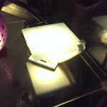
Additionally, looking at the lamp from the side is really really bright because of the bare 1W LEDs. I kinda planned for this and put some slots in the side of the base for some acrylic sheets, but I’m quite done with this design.

This is a test

Quite a while ago, I did some experimenting with laser etching on glass. The intention was to backlight it and make a large lamp with some LEDs behind a large sheet of laser patterned and frosted glass.
Material costs pushed me towards scaling it way down and designing around a small glass tile that I picked up for a few cents. Just for an initial test, anyway.

The tile I chose is about 96mm², and just a hair under 7.3mm thick at the edges.

For the material acquisition side of things, I hunted for high power LEDs from Dealextreme, one of my favourite sites. They carried some 3W LEDs for a couple bucks, not bad. Then I checked Aliexpress. 1W LEDs were substantially cheaper, but I could only get them in quantities of 100. For $12. So I have some extras.

They measured out at around forward 3.2V. Current is about 120mA when the LEDs appear to be at max brightness. Theoretically they should go up to around 300mA, but this is good enough! I can’t see out of the centre of my vision!

I’m not really a huge fan of 3D printers, but I really wanted to crank this thing out quickly and using one freed up any design limitations for this janky part I needed.

After six quick iterations, I came up with this:

Printed Object

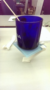
The angles turned out to be tricky to get right, but it worked out. Printed with support material on a Rostock MAX delta printer. The tile is held very securely with no fasteners, perfectly parallel to the base.

Balanced

It even stands up!


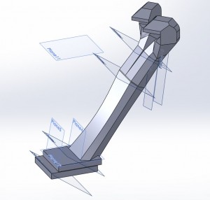
Bonus SolidWorks model view:

SW Lamp

For the actual circuit design, I went with all surface mount for easier custom boards, and some free sample chips from TI. See! That program totally works for them, I’m locked into this design now. Actually, it was the best part for the job that I could find. The LM3410, which is a constant current, analog dimming, PWM output boost converter. Yeah, pretty cool.


I found an Eagle library part that had the same footprint as the LM3410, and then I used my standard “print footprints at 1:1” method to find suitable library parts for my Chinese LEDs and salvage-bin inductor with no datasheets.

Parts list:

  • Inductor L1 – CDRH6D28-3R0NC – 3.0uH, 3.0A
    • The datasheet reference designs used anywhere from 4-20uH inductors. Less inductance just means a little more ripple current, which should be okay.
  • Schottkey Diode D1 – B260A-13, rated for 60V reverse voltage, 2A forward current.
  • Zener Diode D2 – I don’t have this yet! Reverse voltage drop between 21-24V. Might have to stack a bunch in series.
  • 1Ω R1, R3 – Two resistors, 1% tolerance, 1206, in parallel to make 0.5Ω
  • 100Ω R2 – 5%, 0805 for voltage overload.

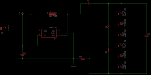
Here are the results of my circuit building:

Lamp Schematic

The schematic is mostly a reference from the datasheet. Max current and voltage limits are a dependent on switching speed, the inductor I used, and the heatsinking of parts, so no hard-and-fast rules. I stretched it to the most high-power LEDs I thought I could get away with. That’s 6. Six LEDs. Worst case scenario, I have to jump one or two of them if everything starts to burn. Best case scenario, I’ve got ten of these boards coming, a dozen inductors, a hundred LEDs, but only three LM3410s.

For this build, I’m trying out the new Dirt Cheap Dirty Board service run by Dangerous Prototypes. I’ve used OSH Park and iTead Studios before, so this will be a fun experiment.


Originally, I was going to etch my own board using a laser cutter and the spraypaint etch resist method. Unfortunately, I have (temporarily, I hope) lost access to the laser cutter. For $14, this seems like a reasonable alternative.


I will update in a month or so, when the PCBs get here.