Archive for June 23, 2014

Knowledge is Power

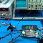
After pulling apart a NDSL, I know a lot more!


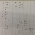
Tracing out the connections, a lot of the LCD pins have a designator silkscreened on, which is totally awesome. I spent a bit of time tracing as many as I could, and then I internetted what I had. That led me to this amazing page, which has the rest of the pin names, but not a lot else relating to this. Totally rad information on other parts of the NDS and GBA systems, though.

Here’s the full(ish) pinout, according to Nintendo:

___NDS-Lite lower screen/lower backlight (P4)________________________________
  1-VDD-5 6-MOD    11-LD1xx 16-LD1xx 21-LD1xx 26-LD1xx 31-LS   36-GND
  2-VDD10 7-GSP    12-LD1xx 17-LD1xx 22-LD1xx 27-LD1xx 32-VSHD 37-COM1
  3-VDD5  8-GCK    13-LD1xx 18-GND   23-LD1xx 28-GND   33-GND  38-LEDA1
  4-GND   9-LD1xx  14-LD1xx 19-LD1xx 24-LD1xx 29-DCLK  34-xx1? 39-LEDC1
  5-VSHD  10-LD1xx 15-LD1xx 20-LD1xx 25-LD1xx 30-SPL   35-REV

That is actually pretty close to the datasheet I’ve been working from. My analysis of where the screens differed was pretty accurate, too, which is cool.

Based on that, here is the NDSL LCD pinout in order, probably, compared to the other one:


Pin Nintendo DS Lite LCD Sharp LQ030B7DD01
1 VDD-5 VDD
2 VDD-10 NC
3 VDD-5 MOD
4 GND SPS
5 VSHD CLS
6 MOD NC
7 SPS VEE
8 CLS VCOM
9 R0 SPL
10 R1 R0
11 R2 R1
12 R3 R2
13 R4 R3
14 R5 R4
15 G0 R5
16 G1 G0
17 G2 G1
18 GND G2
19 G3 G3
20 G4 G4
21 G5 G5
22 B0 B0
23 B1 B1
24 B2 B2
25 B3 B3
26 B4 B4
27 B5 B5
28 GND VSHD
29 DCLK DGND
30 SPL PS
31 LP
32  VSHD DCLK
33 GND VSHA
34 V0
35 V1
36 GND V2
37 V3
38 V4
39 AGND

The signals that don’t directly match the known datasheet are a guess, but usually a pretty good guess (eg. CLS on the datasheet is gate clock, and is in approximately the same pin area as GCK). I’ve gotta go back and check:

  • LS
  • xx1
  • REV
  • LEDA1
  • LEDC1
  • COM1

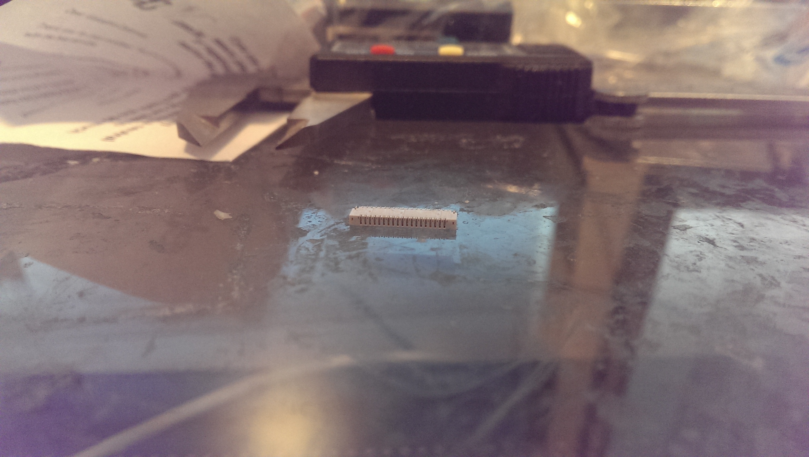
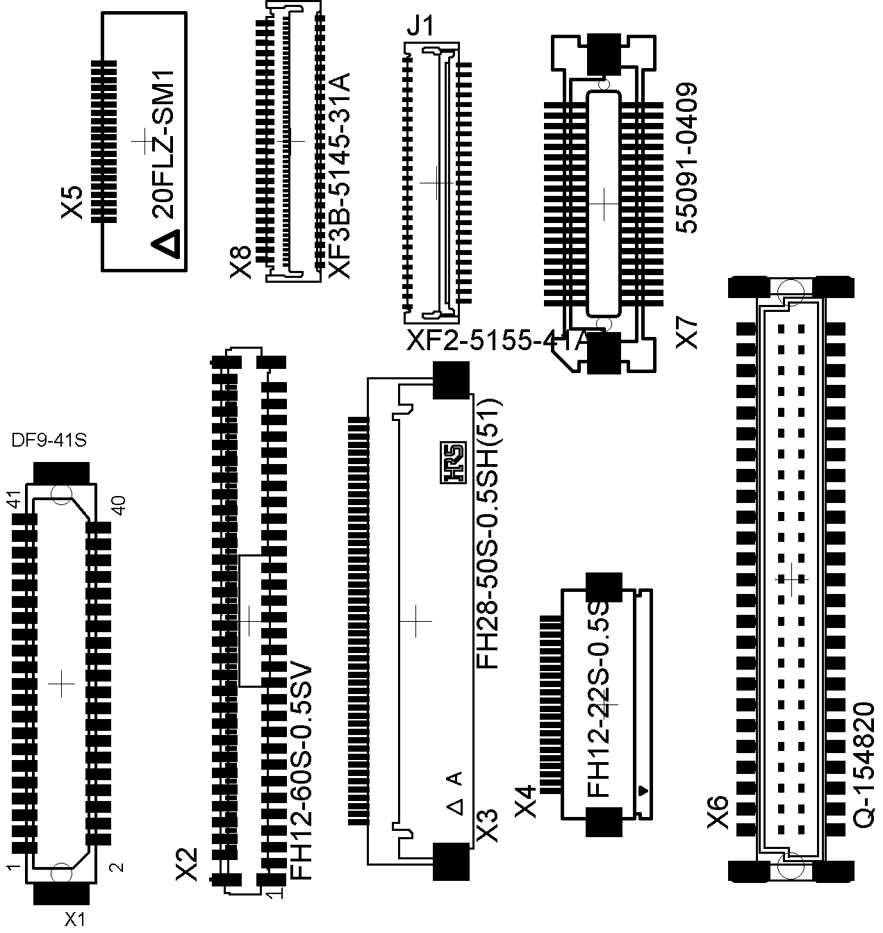
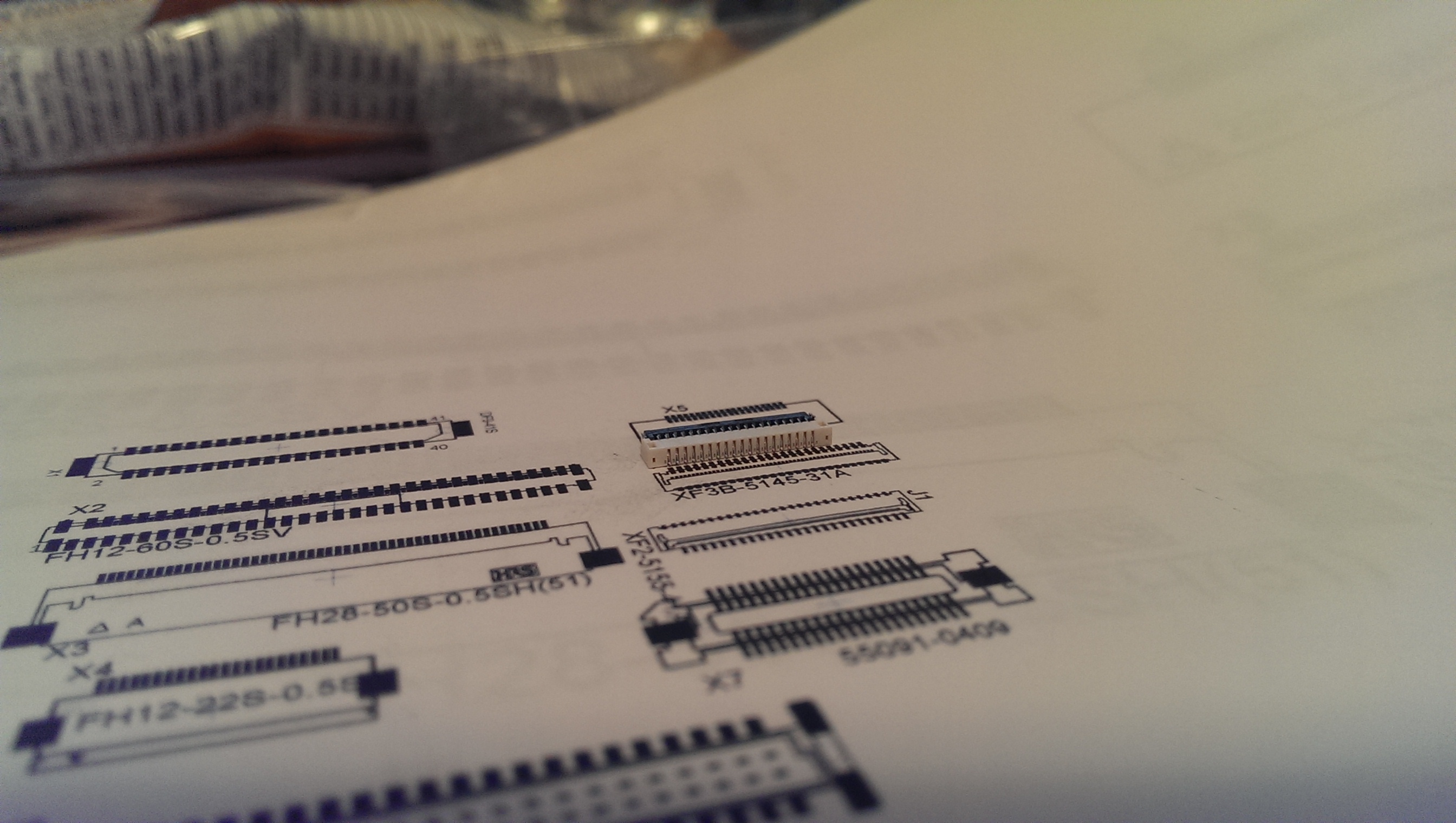
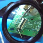
Figuring out the PCB footprint is also tricky from the component alone, and I made a couple mistakes in my earlier assumptions. Fortunately the PCB gave me a little more information, so this is the Nintendo DS Lite LCD connector. Which both gives me a datasheet, and a 50 cent source for more connectors instead of the Chinese manufacturers that market it specifically for the NDSL and charge $2. EagleCAD has a compatible library model from Omron with the model number “XF2C-3955-41A”.

For the touchscreen connectors, they’re 0.5mm pitch, four contacts. That’s a pretty common sizing, and it’s not even a good idea to use the same connectors. That thing totally disintegrated the first time I looked at it funny. A quick search turns up a decent replacement in both top and bottom contact versions, depending on where I want to mount the connector. Eagle part number “52745-0490” from Molex.

NDSL LCD FFC Design (OR: Working with an unknown TFT screen)

I like acronyms. They make me look smrt.

Designing a board to mate with the Raspberry Pi is pretty straightforward.

It’s mostly just a pass-through board. We need a footprint, though. As far as I know, there are no available PCBs out there that people have used the (nonstandard) Nintendo DS connectors on, so no footprints.

First we try the easy way: Asking the manufacturers directly.
alibaba

That doesn’t work very often. Fun story: I once emailed an industrial control company looking for the models for some of their $5000 3-phase power supplies. Having the files would save me probably half an hour while laying out an equipment rack. Twenty minutes later, the customer support team emailed me the internal engineering model file. Complete with PCB model, populated with all components.

I really really don’t think they were supposed to do that. I thought it was pretty funny.

NDS LCD FFC Connector

Here’s the LCD connector for the NDS screen. As you can (sort of) see, it’s 20 pins, and measured a little over 11mm from the first to last pins. With a connector that small, though, exact pitches are still hard to be sure about.
And it’s two rows of pins.

So we go through the Eagle parts libraries looking for something that might work. I kept my eye out for small-pitch 40-pin, double row connector footprints specifically, but I dumped a whole bunch of connectors onto the schematic that might work, after some changes.

Quick layout on the board, and…
SOIC Test Board

…Print it out 1:1 and see what lines up. I used to think that footprint-measuring PCBs were dumb, but I think I’m coming around. Would save me a few minutes and a little printer ink.

The pins lined up with (one side of) the connector labelled XF3B-5145-31A. It’s a 0.3mm pitch Omron connector.

FFC Printout

Good. Using that information, we draw up the new part, and Bob’s your uncle. I don’t know what that phrase means.

LCD Footprint

Side note: The LCD flex cable is pretty standard, and I may try and find an alternate connector in the future. For this, right now, I just wanted a known-good connector and design a PCB around that instead of ordering a big bag of assorted FFC connectors off Digikey.

After drawing the new library parts (touchscreen connector footprint, too, remember), I need to know how to connect everything. In this case, I have an LCD of uncertain properties, a Raspberry Pi GPIO connector of known properties, and a known resistive touchscreen.

For the touchscreen, it gives an analog value (more on that in a future post), so we’ll need an analog-digital converter to get the values to the GPIO. I’m thinking the SX8652 or AR1011, we’ll see. Digikey has them both inexpensively.

The TFT LCD is a little trickier. I wrote in a previous post that someone found a datasheet for the Sharp LQ030B7DD01 that looked similar, but now that I have the DS screen in my hands, I don’t think it is.

NDSL FFC

From what we can see right here, there are 39 pins. Good.

That huge plane that covers most of the top is probably ground, and is connected to pins 4, 18, 28. and 33. Not good. Assuming pin 1 is on the left, the pins don’t line up properly with any single node.

Even if I have any of the above assumptions wrong, the datasheet lists pins 10 through 27 as RGB data lines. Pin 18 must be independent.

If the right side of that image is pin 1 instead, the above problem still exists. There are only 39 pins on the datasheet, so it seems possible that pin 18, near the centre, could be designated as an extra ground pin, but there are 39 physical pins that correspond to that datasheet, so there isn’t really any wiggle room here.

On the right side of the picture, you can see pins 38 and 39 going to some large pads. Those loop around behind the visible flex cable, and then connect to that one you can see on the right. Looks like a backlight control, probably.

Anyway. Those are the reasons I don’t believe this is the right datasheet, but fortunately, there is a “Sharp” logo on the back of the screen. So I do have a starting point for finding a better match.

Going down the internet rabbithole, I found a German-language forum discussing the LCD, which linked to a now-defunct NDSL hacking site, which was conveniently backed up on the Wayback Machine at archive.org.

During that bout of internetting, I came across an antitrust lawsuit that Sharp was involved with, price fixing these screens alongside Hitachi. That means that both manufacturers were producing LCDs with the same pinouts, so that gives me another lead to a possible datasheet. But anyway, it’s probable that the Sharp LCD is LS030B7DD12F, which has no datasheets available online. The Hitachi counterpart is probably 49N07020132, same story.


I guess I need to actually track down a Nintendo DS Lite and really hack it. Damn.