
After building my Piccolo and playing around, I really don’t like the software. It’s certainly simple and hackable and does a lot of what I need to do, but something about the Arduino/Processing pair don’t quite work for me.
Fortunately it’s just a bunch of servo motors, and I already have the PIC code in my toolbox.
Using my Arduino-form-factor PIC dev board and my Bus Pirate as a computer-UART bridge, I wrote in a simple protocol to communicate.
The “communication enable” pin will go high, and then two (might change to three) bytes get sent. The first is an “address” or command, and the second (or second two) bytes are a value/argument.
The 0 address is X axis, 1 is Y, and 2 is Z. The Z only uses binary 1 and 0 for arguments.
The z axi has two states: active and inactive. Inactive/up is the parked position, obviously. The active mode has a hysteresis loop attempting to control the position. The feedback is wired up to a window comparator, like so:
On the computer side, I’m controlling the Bus Pirate with a Python script that feeds it one scalar for a given axis at a time.
The speed at which the PIC executes the movement is controlled in the processor, to be tweaked. I will probably add that command in, when it becomes cumbersome.
As more commands become necessary, I’ll be adding more to the processor, I guess. Maybe eventually I’ll implement a rudimentary G-Code.
Now for the fun part:
Part of my original design goal was to have a 10ns response time. That’s very fast. Most of the old monolithic MOSFETs I’m using (because they’re cheap) have turn-on times in the tens of microseconds.
That totally blows my requirements out of the window, but there are still some optimizations to be made. By using analog circuitry, I can directly control certain parameters and speed them up, compared to hitting a microcontroller and being a slave to a clock source and interrupts getting in the way.
I’ve designed a window comparator. It looks like this:
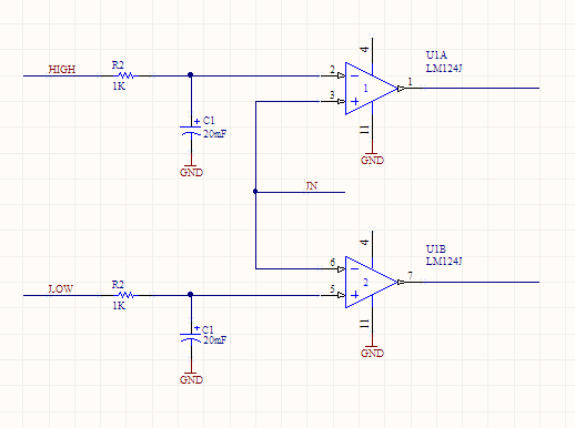
If the input goes above the “HIGH” voltage, then the top output turns on. If it goes below the “LOW” level, then the bottom output turns on. There will be two of these circuits. Feeding these outputs to some discrete logic, or something clever that I haven’t thought of yet, I can turn on or off transistors to the different power stages.
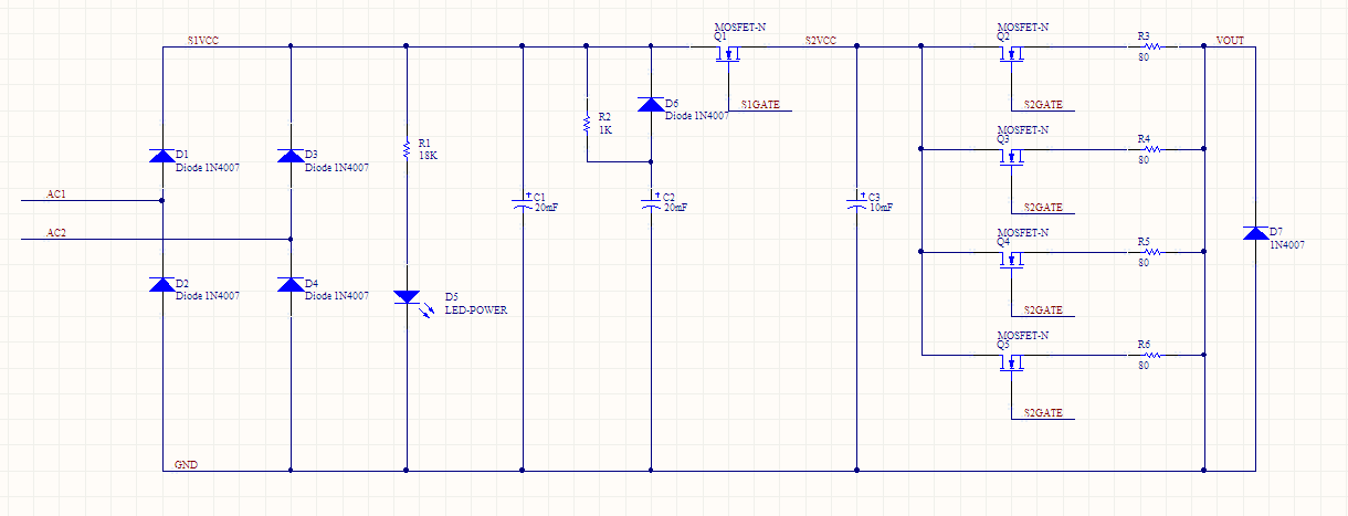
There are three power stages: Stage 1 (rectified input), stage 2(charge), and stage 3 (output).
The S2 MOSFETS can be ignored, just treat them as one. I should be able to parallel as many as I need, within reason, it doesn’t change (most of) the math.
The input of one window comparator is from VOUT, and the outputs are hooked up to the micro. If the HIGH output is on, then that means the MOSFET Q2 is on, but the EDM electrode has not made contact with the workpiece. Start (or continue) jogging the Z axis down.
If the LOW output is active, then we’ve gone down too low, start jogging up.
The other comparator’s input is at S2VCC. That controls the turn-on and turn-offs of the MOSFETS. If C3 is too low, then Q2 must be shut off and Q1 turned on to charge it up. When it is high, flip that. The idea is that Q1 and Q2 should never be on at the same time, providing a direct path to ground. The logic here will also involve halting the Z jogging, or making it jog up.
So there you go. With two different kinds of hysteresis going on at once, there will be some experimentation going on with how they work together. That leads me to one last trick:
You see the HIGH and LOW inputs on the comparator circuit? Those must be an analog voltage. That I’m going to set with a PWM out on the micro and the caps smoothing it out to an analog value. Varying the duty cycle of the PWM will allow me to vary the analog voltage.
Counting up my PWM outputs:
Two for each window comparator (4 total)
One for each axis (7 total)
One for the oil pump (8 total)
I haven’t discussed that last one yet, but stay tuned!