
I’m on another clock kick. More of a wristwatch this time.
The dream is to have a couple metal bars floating in oil, and when a button is pressed, they float to the appropriate hour and minute positions.
For an initial version, I’m paring this way down to just a single indicator hand.
On the mechanical side, I start with some preliminary sketches.
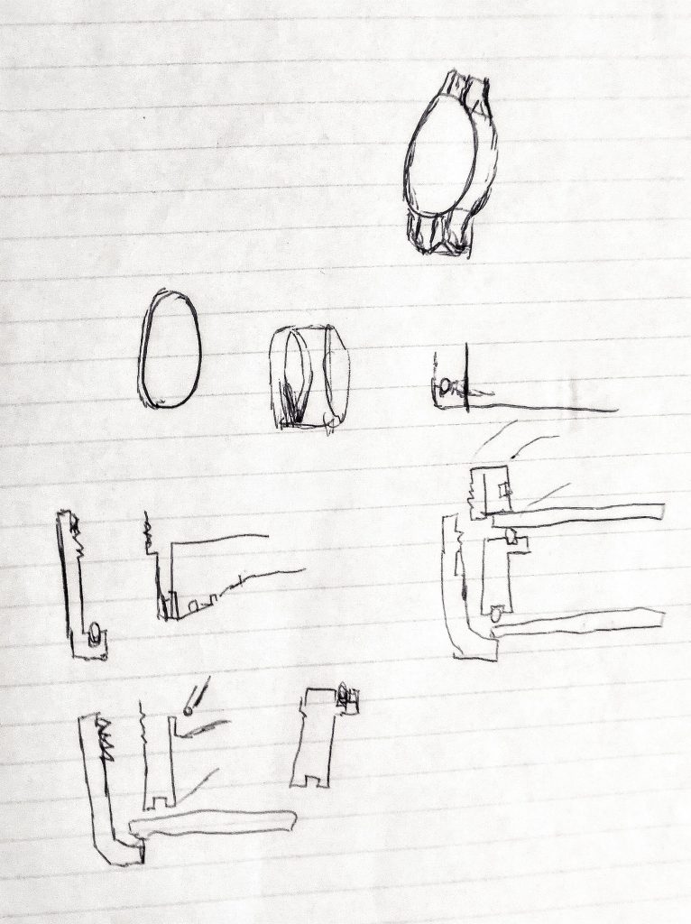
There were many more, with very little polish in any of them. They’re just to get the mechanicals down and direct the overall thrust of the design.
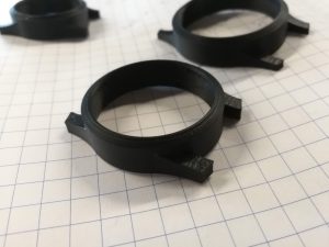
Watch crystals are quite inexpensive from China, so I picked up a selection of sizes, and while waiting for shipping, I modeled and 3D printed some tests for the three most likely candidates. Shown here are cases I designed for sizes 30mm, 34mm, and 38mm faceplates, but you really can’t tell that they’re different sizes in pictures. The 38mm one seemed to fit best on my wrist, so that’s what I went with.
Rolling my sketches into the CAD, I came up with this:
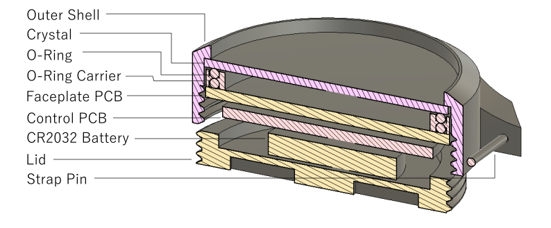
The main body is just a shell with internal threads, and inside there’s a stack-up consisting of:
- 1.2mm crystal face
- 37mm OD x 1.5mm o-ring
- Double sided o-ring retainer
- Another o-ring
- 15x3x1mm neodymium magnet
- Faceplate PCB
- Control PCB
- Coin cell battery
- Threaded cap
Dimensionally, it’s a very tight system. It doesn’t really fit with the battery, so stuff will have to be moved around. The o-rings are there to seal in the oil, which is kinda fun.
Jumping to the electrical side, I need some electromagnets.
A guy named Carl Bugeja has designed coils drawn out in PCB traces to make a PCB motor. He shows off the design a lot here.
Included, naturally, are a set of gerbers which were worth ordering to play around with.
I tossed a magnet on there and was able make it jump around the coils using a small bench power supply. The resistance at each phase was about 12 ohm, the same value that Carl Bugeja measured. Each phase does go through three entire coils, however, so assume 4 ohms per coil.
The coil pattern is illustrated quite well with Carl’s coloured gerber export:
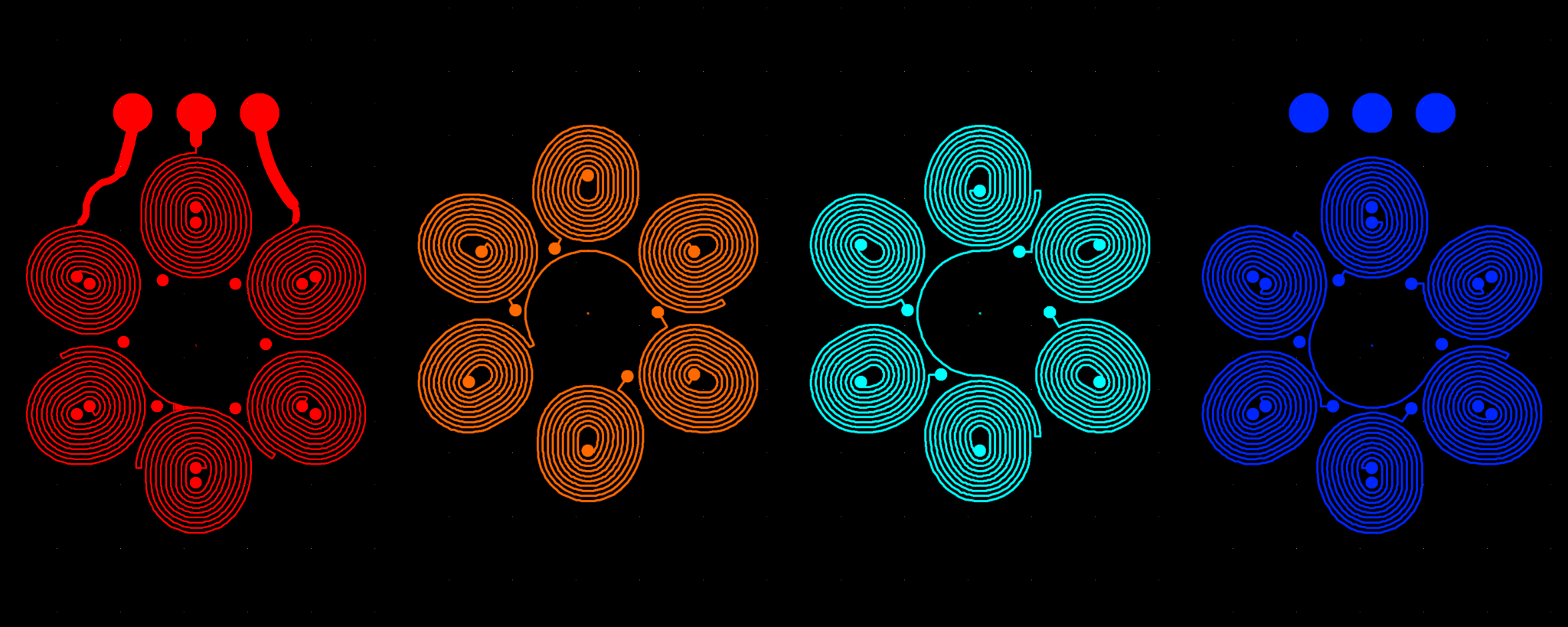
Application of the right hand rule shows that as current goes in a clockwise spiral direction (curl your right-hand fingers in that direction), your thumb will point in the direction of the magnetic field, out of the screen. Interestingly, the ordering of the coils on the layers isn’t from top to bottom. Carl ordered it from layer 1(top)->layer 3->layer 2->layer 4(bottom). Probably to (very very slightly) increase the length of the current path and therefore the resistance of the coil.
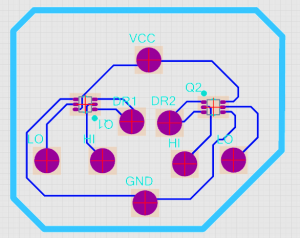
To drive a coil with any polarity we like, we need a standard H-bridge circuit. A future version might do some interesting stuff with that, so the fine control that an H-bridge provides is kinda cool. Generally an H-bridge consists of a couple matched pairs of transistors of opposite substrate. Poking around, there’s a single chip MOSFET solution that looks suitable, the VT6M1.
So here’s a quick PCB layout of how that would work:
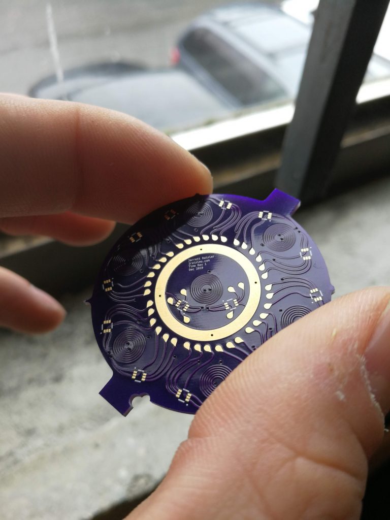
But of course, just dropping that into a board is boring! We’re going to make a pretty PCB, we might as well go all the way! I’ve spoken before about PCBModE. Using my tool to convert the above PCB into a compatible format, I pull it into PCBModE, cleaned it up, added some electromagnetic spirals, and a little bit of flair. There are solder pads to hook this PCB up to another PCB, containing all the brains.
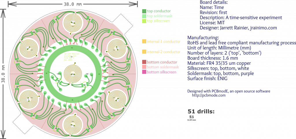
Figuring out a compact way to drive all those connections is somewhat challenging. With six coils around the perimeter and one in the centre, a “drive high” and “drive low” connection for each side, there are 28 signals, plus power and ground. All of those need to be transferred out to a “controller” PCB, so I added those green teardrop solder pads. The idea being that pins are to be soldered onto them, and then pushed into through-holes on the controller PCB.
For the controller, after all of the through-holes that connect to the above-mentioned solder pads are placed, space is very tight! Investigation of various shift registers and their sizing yields no encouraging results. NXP has a cool line of miniature 74HC series logic, but even those don’t fit in my given space.
Fortunately, there is a nice STM32 part I was able to squeeze in.

Despite actually being designed in ECAD software, I think it turned out quite beautiful in its own way.
Some first revision woes:
In retrospect, this was a terrible way to design the electronics. By putting the MOSFETs on the faceplate PCB, I maximised connections needing to cross to the other PCB, and minimised space on the controller by filling it up with through-holes. By crossing with the coil connections directly, I would have needed only two wires per coil, instead of the six that the H-bridge is requiring (plus grounds).
An unregulated coin cell is just about the worst possible power supply for a miniature, portable, long-running device that can’t be opened easily, and leaks oil when it does get opened.
Additionally, I was rushed to get PCBs out and forgot to add a button to activate the watch face.
Next version, with more time, will include improvements for all of the above, as well as a proper external RTC, and LiPo battery circuitry.
Jumping back into the mechanical side:
Everything was 3D printed to test fit. Surprisingly enough, threads worked pretty well. There was a ton of stringing in the internal threads, though.
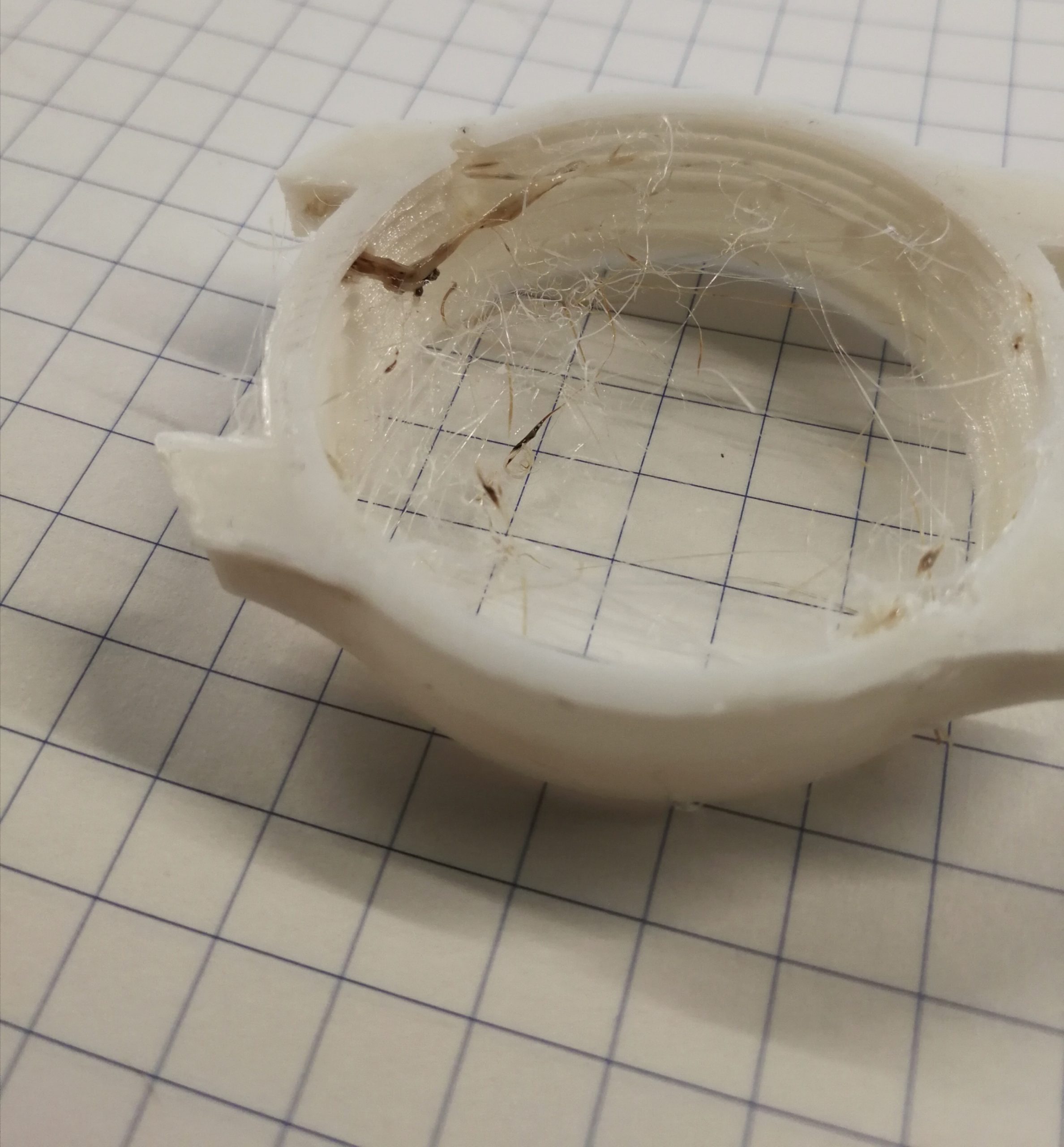
Initially, I was using a knife to clean those up, but that got old quick. Additionally, oozing from the print of the outer threads made it a little tough to mate for the first few cycles. So I printed a tap. You can see the taper on the leading threads, and the notch to clear out the chips.
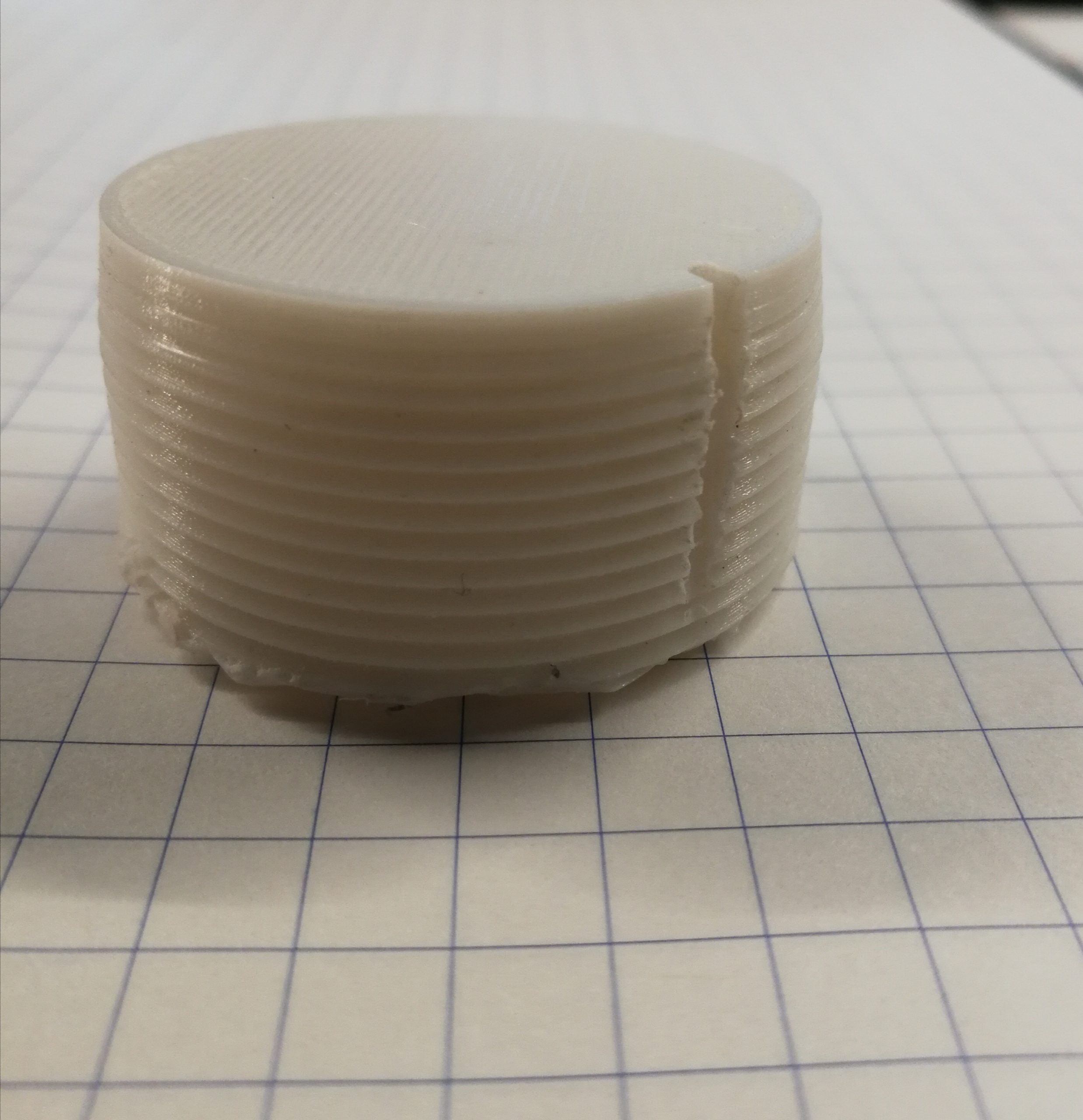
That worked great! Passing it through the system a couple times made the threads work easily.
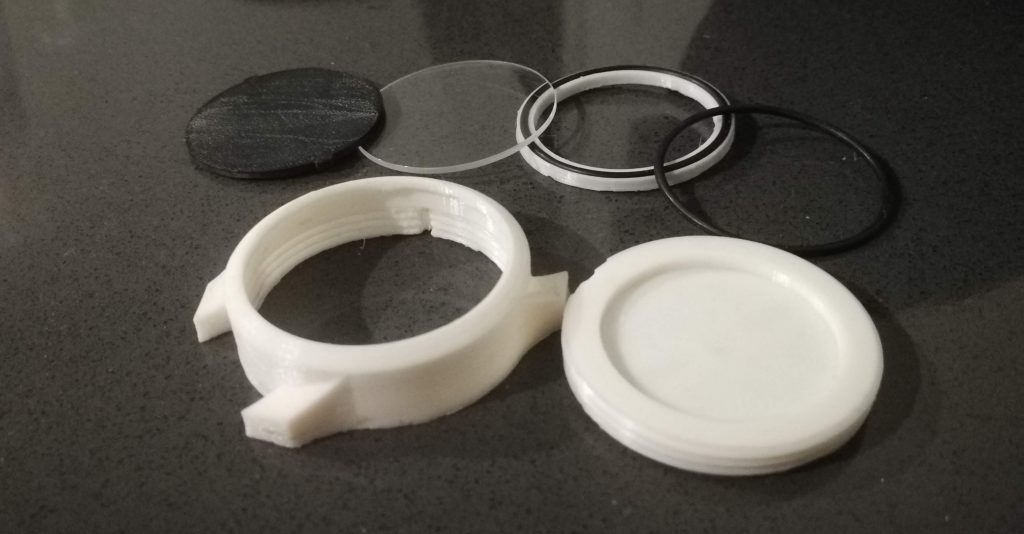
Here all the non-electrical components:
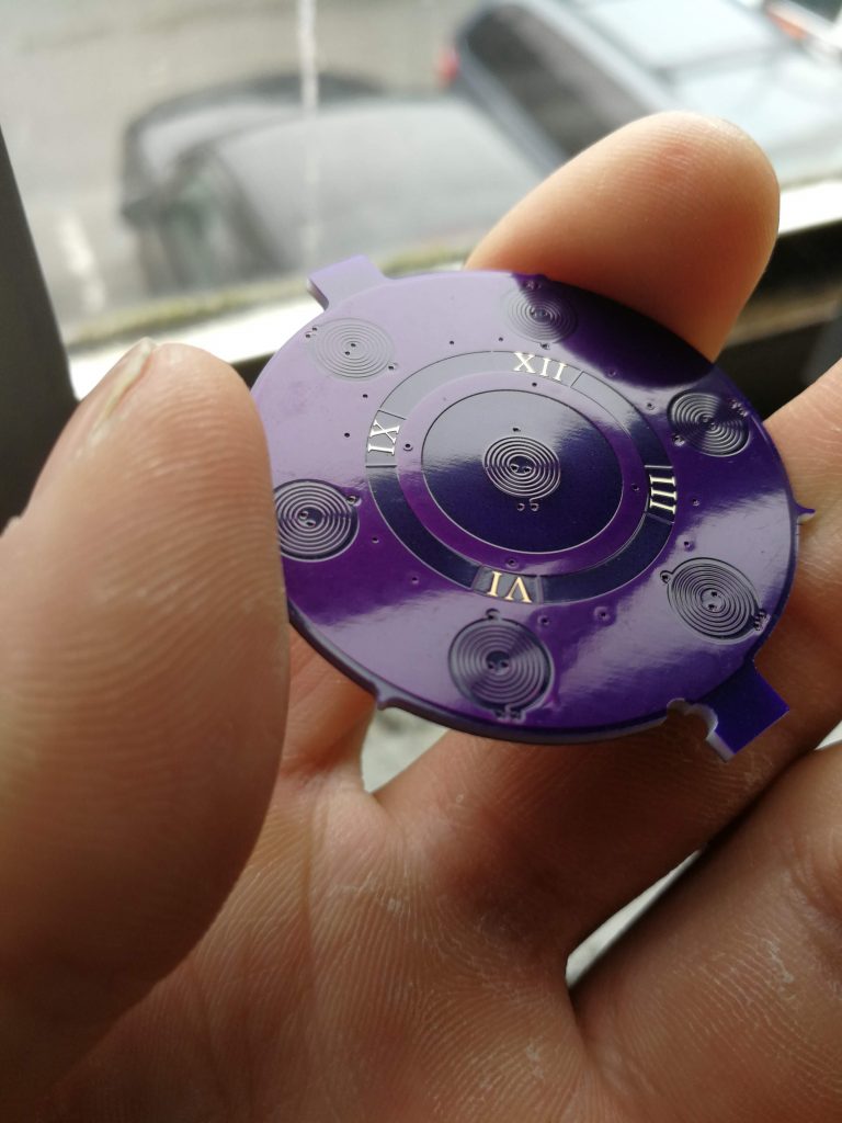
Here is the faceplate PCB:
And, assembled:
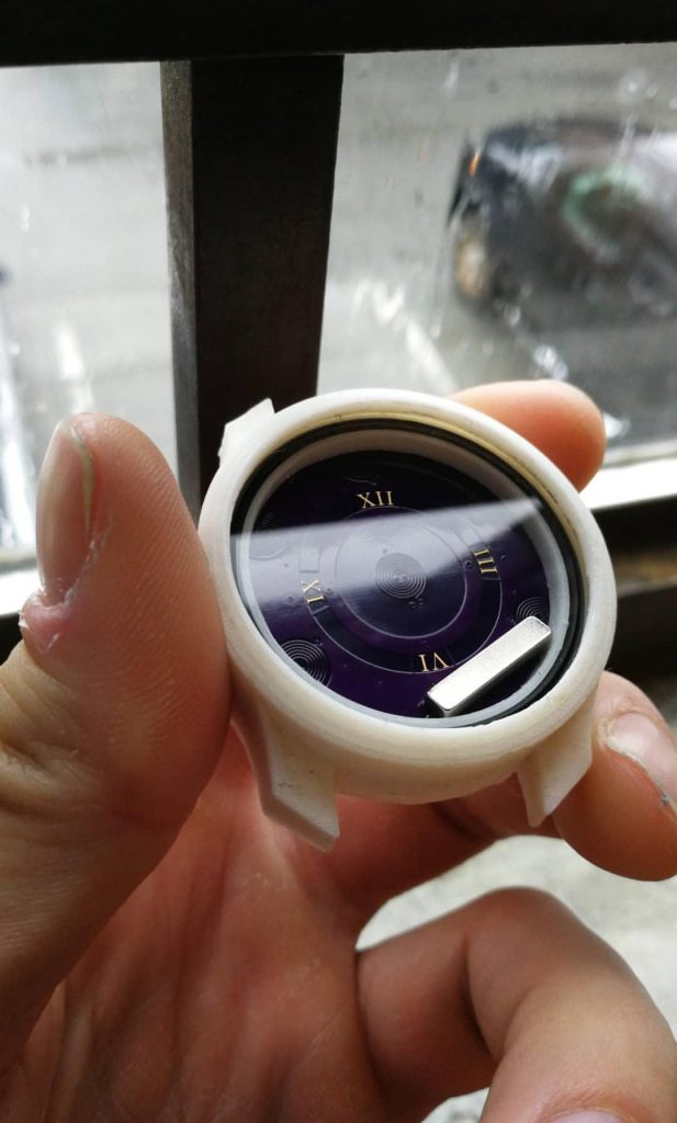
Testing the coils directly with a benchtop power supply once again made the magnets jump around.
And then adding the H bridge transistors and testing with a low current signal to control the direction of the magnetic field.
Status: super cool. Listen to that click!
For prototyping, everything is 3D printed. The goal would to mill it all out of aluminum and then anodise it dark blue.
The o-ring holder needs to be lathed or otherwise made out of a solid material, too. 3D printed parts are going to have a bad time if I try to use them to seal an oil filled cavity with porous plastic.
I got the endorphin hit I needed out of this for now, though – Some interesting concepts have been demonstrated, and perhaps I’ll come back to it another day to add polish.