Archive for PCB Art

Force-Directed Circuit Board Footprint Autoplacement

From Wikipedia:

Force-directed graph drawing algorithms are a class of algorithms for drawing graphs in an aesthetically-pleasing way. Their purpose is to position the nodes of a graph in two-dimensional or three-dimensional space so that all the edges are of more or less equal length and there are as few crossing edges as possible, by assigning forces among the set of edges and the set of nodes, based on their relative positions, and then using these forces either to simulate the motion of the edges and nodes or to minimize their energy.

Force-directed graphs are a common way to display things like mind-maps. It’s a good way of spreading out the whole collection, while grouping related items together, and minimizing the path length between the closely related items. In my mind, this has a lot of similarities with how PCBs are laid out.

Well, there’s only one way to prove that theory.
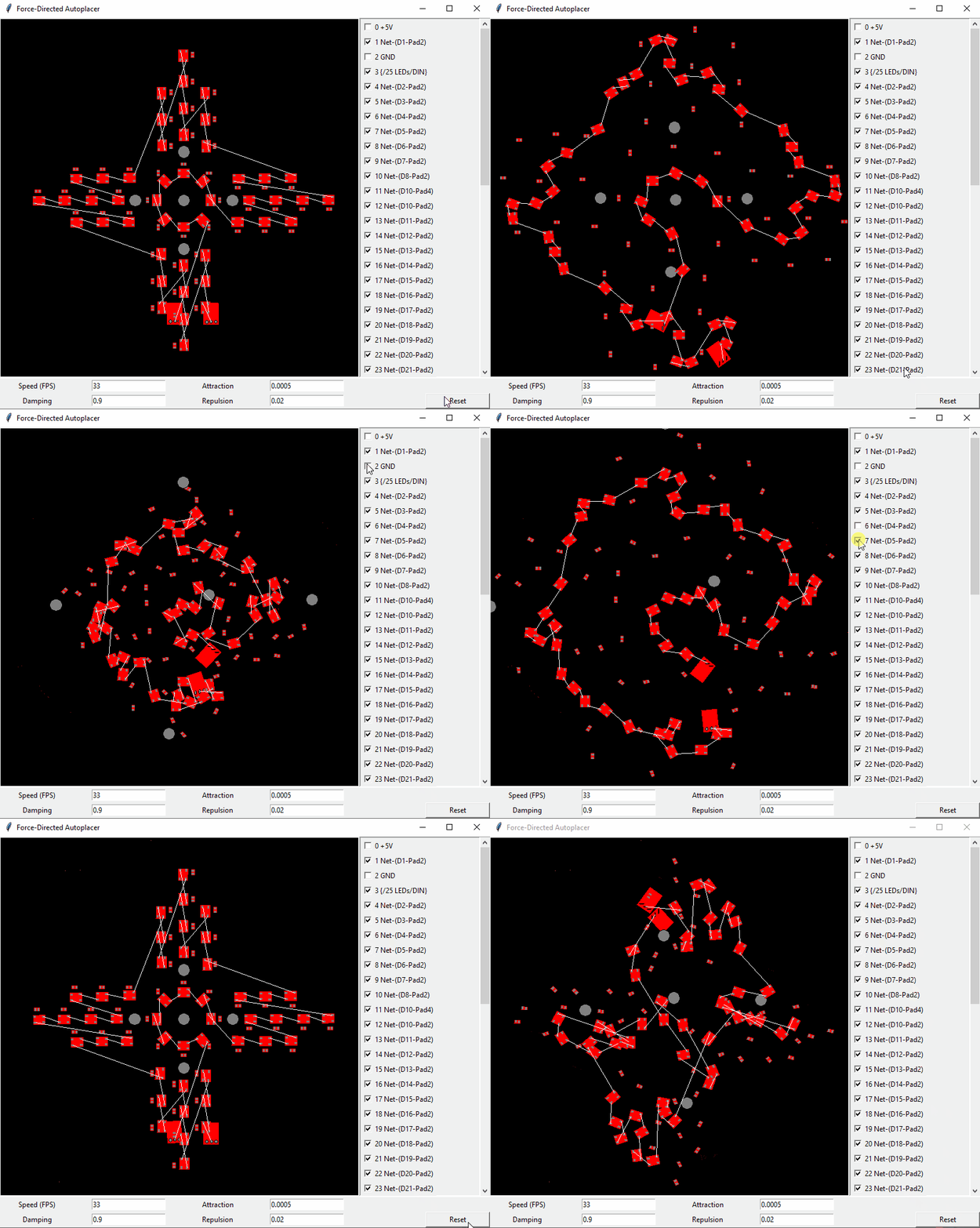
KiCad Footprints animated in an exploding fashion

Using KiCad PCB parsing code I wrote for another project, I was quickly able to grab the nets and footprints out of a KiCad project. Displaying the nets and allowing specific ones to be turned off was a feature I identified as critical early on, because the ground or power nets would overwhelm any of the others, rendering the important nets useless.

Truthfully, a significant part of this was wrangling TKInter to build the Python GUI that I wanted. It was a success, but I’ve never used it before, and I am not a fantastic UI designer.

Under the hood, the system essentially treats each of the nets as a spring, and applies a simplified version of Hooke’s Law to each connection. Each of the centre point of the footprints acts as a charged particle, and a simplified version of Coulomb’s Law acts upon it to repulse all of the other footprints. These algorithms are a pretty typical way to do this, by essentially setting up a physics simulation. One tweak on this strategy that is unusual, is that the nets don’t act on the footprint origin. They act on the pad itself, which allows a torque to impart a rotation on the footprint.

I’ve gotten this project as far as “fun tech demo”, and it’ll likely fall dormant for a while in this state. At some point, I will build an appropriate PCB using this technology, because I love making unusual designs that are electrically fine.

The repo is here. Have at it.

Sugar Glider Wifi Throwies


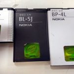
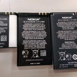
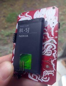
I have access to a big box of Nokia phone batteries. This is a problem. It is very large. I do not have enough Nokia phones to use them all.

There are three sizes:

BP-6MT (1050mAh), BL-5J (1320mAh), and BP-4L (1500mAh).

After some catalog-hunting (be vewwy vewwy quiet), I’ve found the connector they use, the A117827CT-ND.


Update: This handy website has sizes of various batteries listed.


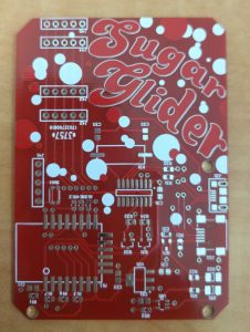
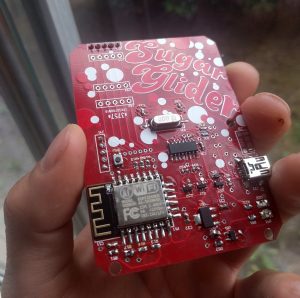
This PCB – I call it “Sugar Glider” – is a battery-powered ESP8266 wifi module. It supports charging a single LiPoly/Li-Ion battery over USB, running off the battery, or both while it’s plugged into your choice of MicroUSB or Mini USB connector.

Mostly using the reference design of the MCP73831 charger chip, and it powers an ESP8266. There is also a CH340G USB-serial chip for programming, so it basically acts like a NodeMCU.


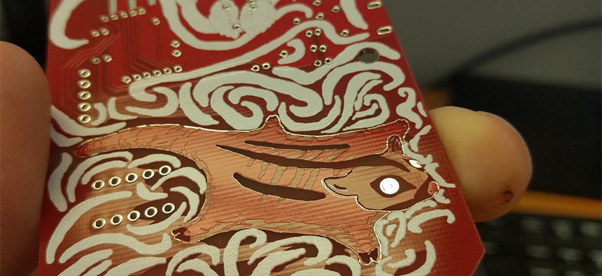
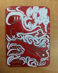
But wait, there’s more! Despite the simplicity of the design, and really not caring that much about it, it took a tonne of time. That’s because I’m rusty at drawing from not having done any in the last decade, and it looks like this!


This was done by exporting gerbers, converting each layer to B&W images, then loading them up in my (also decade old) copy of Photoshop. They were coloured according to my sampled colour palette, and then drawing commenced.

When I was done, they were loaded back into CircuitMaker using the techniques detailed here and here. I think I’ll try to do more of this in the future. Having this much unused PCB space is rare, though – It was needed to act as a sled for the batteries, so it’s quite large. Usually I make boards as small as reasonably possible to save on costs.


The assembly went reasonably smoothly. You have a choice of populating the micro- or mini-USB connections. I prefer the mini, because there are something like 20 different possible microUSB connector footprints. In future versions, I’ll probably also use a 0-ohm resistor to select which one. Having an unpopulated connector on the same line is a recipe for bad signal integrity and unwanted antennas.

The power supply portion of this is simply a low-drop out (LDO) linear regulator, because I wanted to bang this circuit out quickly without having to design a switch-mode power supply (or: the Right way to do this project). Slight problem: the LDOs I sourced from China, well, weren’t very LDO. They had a full volt drop across them, leading to 2.7v seen on the ESP8266 at nominal battery voltage. No bueno.


The solution is very simple; just replace the regulator with a proper part from Digikey, that comes with a datasheet. Modern ones are usually closer to 0.2v. That’s the stuff.

This project was created in CircuitMaker. Here’s a link the cloud project page, but here is a zip file of all the relevant files – Schematics, PCBs, gerbers, and layer drawings. The resource-heavy images don’t play nicely with PCB design, so I recommend deleting them while editing the PCB, and then adding them back in right before export.

Cosmetic Surgery on Altium Boards

I’ve been a really big fan of PCBModE for a long time. Designing beautiful PCBs is a seriously difficult skill, and a serious abuse of the PCB board houses. Saar Drimer of Boldport has done a great job, and anyone reading this should definitely check out his stuff.


Where it falls down, though, is doing complicated and electrically correct circuits – No DRC/ERC rules, and not even a schematic view. I use Altium for my main PCB package, but it’s pretty tricky in it to get images into the PCB. It is possible, if a little convoluted, so here is my method.


Part of the problem is that I’m using Altium Designer 10 – Newer versions are better with this, it seems.


This process uses the CreateRegionsFromBitmap script. On my machine, it’s located in:

C:\Users\Public\Documents\Altium\AD 10\Examples\Scripts\Delphiscript Scripts\PCB\CreateRegionsFromBitmap

It’s also broken and required a couple fixes.

When I opened up PCBLogoCreator.PRJSCR in Altium and compiled/ran it, I got an error, missing semicolon at this line:

GrayWidth := Round((1 - sqrt(GrayProportion)) * PixelToCoordScale / 2);


Instead of trying to fix it (I don’t got time for that), it was replaced with:

GrayWidth :=0;


Second error was a missing function. This was fixed by copying LayerComboBox.pas from the PCB Logo Creator script into the working CreateRegionsFromBitmap script directory and project tree.

Then hit Run, and a dialog box pops up!


My workflow here was to identify what different shades I could get on the PCB, and the best ones for my image.


Here is a list of portions that contain wildly different shades:

  • Bare FR4
  • Copper
  • Soldermask
  • Soldermask with copper underneath
  • Silkscreen


Predictably, that means that images with 5 or fewer colours (including backgrounds and outlines!) work best. For a non-commercial practice piece, Dr Seuss was the clear choice.

First step is to pull the desired image into Inkscape and separate all the component colours.

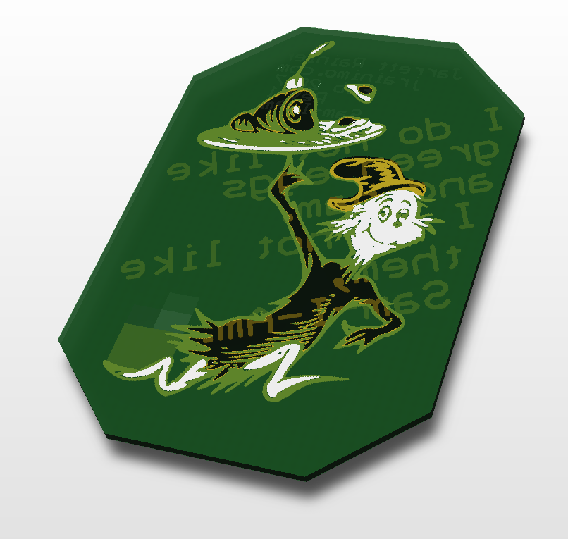
The way Inkscape handles colours masking each other – like the yellow layer being the “background” and relying on it being blocked by the colours on higher layers – doesn’t really mesh with the way they show up on PCBs. After some fudging around (as quickly as possible), this is what I came up with.


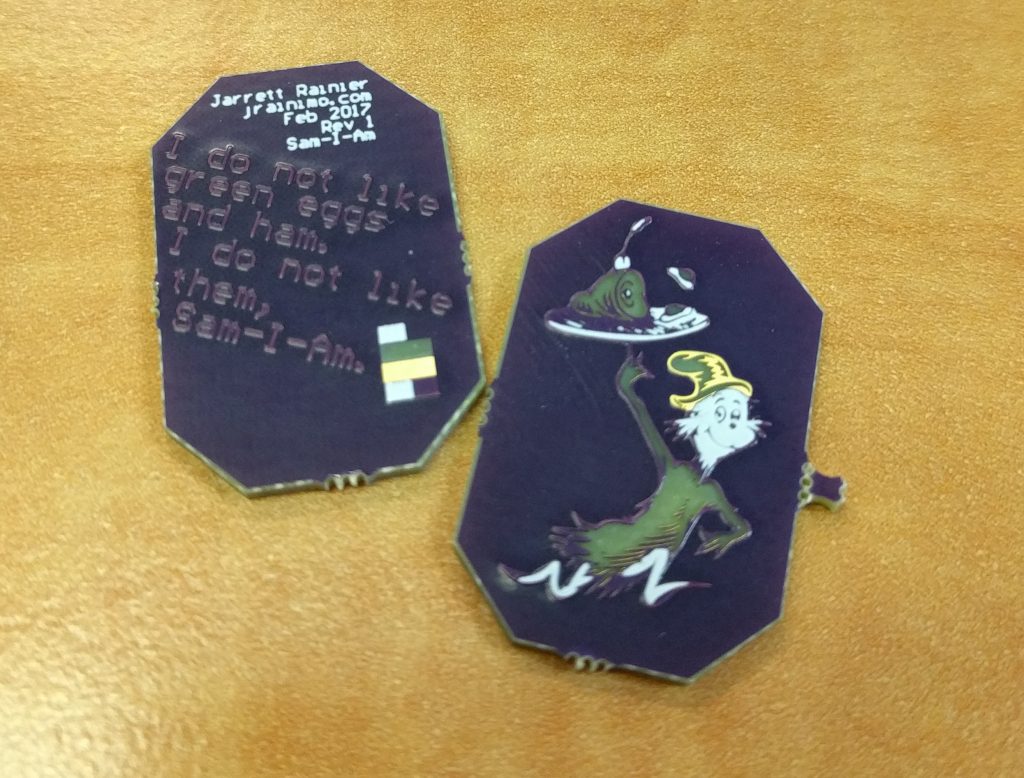
And here’s how the PCB turned out in OSHPark Purple.


The thing is super small, so you can see how the soldermask pools up against the raised copper and causes weird bubbles.

I didn’t spend a huge amount of time trying to fit the best colour scheme to the image. But what I’ve done since then is scanned a few PCBs that I have kicking around, and created this handy palette for a various soldermasks!

The best method for using these is probably to ignore the PCB aspect entirely at first, and draw a pretty picture in your illustration application of choice, using just those colours. Translating that to PCB is the secondary concern, and much easier. Something to note is that the “copper” colour of the DirtyPCBs palettes is HASL tin grey on top, and the OSHPark scheme is ENIG gold on top. Both of those are shiny.

Another technique worth trying is crosshatching. That might work out really well, in the same way that it works for laser cutting.