Archive for Relapse

Closing the Loop

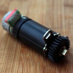
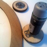
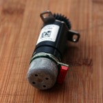
Here is the motor that I’ll be using. I don’t know if I mentioned this already, but I’ve got a big bag of these things. I don’t know where they originally come from, and I can’t find any sort of datasheet or description on the internet.


But that’s okay. I can work around that. I didn’t even know what kind of motors they were until I poked around with a multimeter. Turns out they’re brushless DC motors, which is pretty cool for both accurate positioning and speed, but relatively difficult to control.

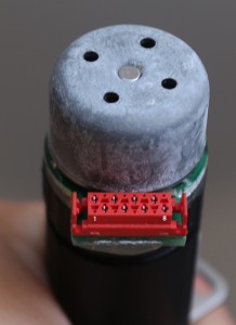
Here’s the pinout, from left to right:

BLDC Pinout

  1. Winding A
  2. Hall Effect sensor A
  3. Winding B
  4. Hall Effect sensor ground
  5. Winding C
  6. Hall Effect sensor B
  7. Hall Effect sensor power
  8. Hall Effect sensor C

Finding the windings was easy, I just checked the resistance between pins. My highly sophisticated method for finding the sensor pins, though, was putting a voltage across them and watching for smoke. I guessed wrong the first time, so, uh, make that three motors I’ve sacrificed, all told.

The output on the Hall sensors(powered by 3v) are very low, so they need to be hooked up with a differential amp to a potentiometer. The motors draw about 800mA at full load.

Because I have a whole bunch of these motors, I’ve been doing research for the absolute cheapest way of controlling these. Most of the controllers chips I’ve found are right around the $15, which is ridiculous.

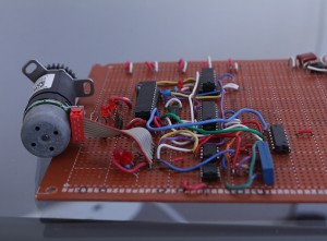
So I built a quick test protoboard because it was cleaner than a breadboard, but it ended up getting a little complicated.

 BLDC protoboard

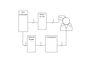
How I’ve got it right now:

Closed loop BLDC motor control

 While building this, I finally found an affordable solution, the MC33035. It was about $2. But hey, at least I’m intimately familiar with these motors in a way that a one-chip solution wouldn’t give me, right?

Here’s the test-code for PIC that I wrote. I still have maybe 30 of these motors, so they definitely could come into play in future projects. So, one-chip solution aside, I’d add forward/reverse control, PWM speed, and potentially speed/position feedback so I could include a PID loop. That would be pretty cool.

#include <htc.h>
//Int osc, wdt disabled, mclr disabled, bor, fscm
__CONFIG(0x3F1B);
#ifndef _XTAL_FREQ
 #define _XTAL_FREQ 96000
#endif
//HALL EFFECT
#define PHALLA RA0
#define PHALLB RA1
#define PHALLC RA2
#define SENSEA RB5
#define SENSEB RB4
#define SENSEC RB3
void forward(void) {

    //AC', AB', B'C, A'C, A'B, BC'
    if(PHALLA == 0 && PHALLB == 0 && PHALLC == 1) { //Step 1
        PITCHA = 1;
        PITCHC = 0;
        ENB = 0;
        ENA = 1;
    } else if (PHALLA == 0 && PHALLB == 1 && PHALLC == 1) { //Step 2
        PITCHA = 1;
        PITCHB = 0;
        ENB = 1;
        ENC = 0;
    } else if (PHALLA == 0 && PHALLB == 1 && PHALLC == 0) { //Step 3
        PITCHC = 1;
        PITCHB = 0;
        ENA = 0;
        ENC = 1;
    } else if (PHALLA == 1 && PHALLB == 1 && PHALLC == 0) { //Step 4 
        PITCHC = 1;
        PITCHA = 0;
        ENB = 0;
        ENA = 0;
    } else if (PHALLA == 1 && PHALLB == 0 && PHALLC == 0) { //Step 5
        PITCHB = 1;
        PITCHA = 0;
        ENC = 0;
        ENB = 1;
    } else if (PHALLA == 1 && PHALLB == 0 && PHALLC == 1) { //Step 6 
        PITCHB = 1;
        PITCHC = 0;
        ENA = 0;
        ENC = 0;
    } 
    SENSEA = ~PHALLA;
    SENSEB = ~PHALLB;
    SENSEC = ~PHALLC;

}
void main(void){
    ADCON1 = 0x07; //disable ADC
    CMCON = 0x07;
    TRISC = 0x00; //Port C Tris output
    TRISB = 0x00; //Port B Tris output
    TRISA = 0xFF; //Port A Tris input 

    while(1){
        forward();
    }
}

Edit, 6/12/2017:

It’s very weird to see something from legitimate sources start to appear as grey market goods, several years later.

I came across this and this item on AliExpress.

In case those links disappear (likely), it’s billed as: AIYIMA 2pcs Micro DC Brushless Motor 22MM Planetary Gear Motors External Rotor With Hall. The markings on the visible label read 4086013, 172336, and XF08F4901147. On the product page itself, the motor claims to be a AIYIMA-A4F321. The markings on the version I have, however, read 15246014, 172289, and XF04B4000507. Hopefully that helps someone.

The first link is a plastic shaft version I haven’t seen before, while the second link is the metal version that looks identical to my own.

Final pictures

Software

I’ve opened up two sacrificial motors, and they definitely seem to have some sort of on-board Hall effect sensors. I haven’t looked for the pinout yet, but chips were all labelled 1036 for one of the motors, and J588m for the other one. Google turns up nothing about these (that I can find).

The motor connector has eight pins, three of which are used up by the motor windings A, B, and C. That means two of the remaining pins are probably VCC and GND. The last three pins must be the Hall sensor outputs.

Currently, I’ve only got the motor running in open loop. That results in a working, but pretty crappy rotation. When I have some time, I’ll grab the feedback, and close the motor loop. Here’s the PIC code I have right now:


#include <htc.h>

//Int osc, wdt, mclr disabled, bor, fscm
__CONFIG(0x3BD4);

#ifndef _XTAL_FREQ
 #define _XTAL_FREQ 4000000
#endif

//Pres butan
#define PITCHFW    RA4
#define PITCHRV    RA3

#define YAWFW    RA2
#define YAWRV    RA5
//Outputs

//Motor variables (RC0, RC1, ETC)
#define PITCHA    0
#define PITCHB    1
#define PITCHC    2

#define FLOATA    3
#define FLOATB    4
#define FLOATC    5

//String constants
#define PITCHMOTOR    1
#define YAWMOTOR    0

//AC', AB', B'C, A'C, A'B, BC'
#define FORWARD        0
//BC', A'B, A'C, B'C, AB', AC'
#define REVERSE        1

unsigned char iPortCValue, iPitchStep, iYawStep;

void set_bit(unsigned char iAddress, unsigned char bBit) {
    iPortCValue |= (1<<bBit);
    PORTC = iPortCValue;
}    

void clear_bit(unsigned char iAddress, unsigned char bBit) {
    iPortCValue &= ~(1<<bBit);
    PORTC = iPortCValue;
}    

void delay_motor(void) {
    unsigned char i, e;
    for (e = 0; e < 6; e++) {
        for(i = 0; i < 170; i++) {
            asm (" nop ");
            //__delay_ms(1);
        }
            CLRWDT();
    }
}

void move(unsigned char iDirection) {

    delay_motor();

    //AC', AB', B'C, A'C, A'B, BC'
    switch (iPitchStep % 6) {
        case 0:        //AC'    AB'C'    
            PORTC = 0x29;
            break;
        case 1:        //AB'    AB'C    
            PORTC = 0x19;
            break;
        case 2:        //B'C    A'B'C    
            PORTC = 0x34;
            break;
        case 3:        //A'C    A'BC    
            PORTC = 0x2C;
            break;
        case 4:        //A'B    A'BC'    
            PORTC = 0x1A;
            break;
        case 5:        //BC'    ABC'    
            PORTC = 0x02;
            break;

    }
    if(iDirection == 1) {
        iPitchStep++;
    } else {
        iPitchStep--;
    }        
}    

void main(void){
    OSCCON = 0xF1;    //Internal osc
    TRISC = 0x00;    //Port C Tris output
    TRISA = 0xFF;    //Port A Tris input    
    iPortCValue = 0;
    iPitchStep = 0;
    iYawStep = 0;
    int i = 0;

    while(1){

        //if(RA2 == 1) {

            for (i = 0; i < 36; i++) {
                if(RA5 == 1) {
                    move(1);
                } else if (RA4 == 1) {
                    move(0);
                }
            }
            for (i = 0; i < 200; i++) {
                delay_motor();    
            }
        //}            

    }
}

Problem identification. The doldrums.

At this stage in the game, this project is on a clear path to completion, with no major revisions in sight. What I’d like to do is identify some issues that have made themselves apparent during the build and tweaking processes. Some are things that I would fix in the version 2, if one were to exist. Some I need to fix right now.

This also marks the end of the “let’s build something cool!” phase and into the “ugh. WHY isn’t this working?” phase. It’s a lot harder to stay interested in finishing, but I’m going to power through.

Here’s where I’m at:

  1. Limited rotation: any rotational movement that goes too far would tangle up cables that are driving the pitch gear motor. Everything in this system is designed to be battery-powered, so the obvious solution would be to mount the yaw motor on the rotating platform. That could mesh with an inside gear that’s been fixed to the base.
  2. Non-prime gears: this is one of the topics that have come up while doing ongoing research for what constitutes a “good” mechanical design. Generally, teeth shouldn’t continually mesh with exactly the same tooth and the opposing gear. That’s a good way to cause excess wear through dirt or inconsistancies in the the teeth hitting the same spot every time. To make sure that doesn’t happen, you want the gears to be co-prime. Right now, my two gear sizes have 55 teeth, and 280 teeth. That’s no good. Fortunately, 281 is prime, so that neatly solves that problem. The pitch gear doesn’t ever rotate all the way through, so that doesn’t fix the issue for those mates, but there’s nothing I can do about it, so why worry?
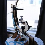
  3. Catching: the top gear(I’ve been calling it the pitch gear) catches up between the two gears providing support. When it gets caught, the gear likes to try and shove the rear support struts up and out of the base. This is the only problem(so far) that I haven’t foreseen. Fortunately, I was able to move that top support gear a little closer to the bottom portion using some holes that already existed. Anything less than 90 degrees seems to do the trick.
  4. Squeezed bearings: I used some flat washers on either sides of the bearings, but that still caused too much friction for them to rotate properly. I need to find some smaller nylon washers, or maybe flanged bearings.
  5. Wobbly base: the lower gear(I’ve been calling it the yaw gear) is mostly just sitting on a huge bolt that I had kicking around. I was hoping it would work, but no dice. It doesn’t quite. The gear wobbles around in relation to the base just enough to lose contact with the motor gear. When I can get some more laser cutting in, I’ll build another base with an additional cage around the bolt to provide more support.

Relapse (Build)

Putting it all together.


The materials I used are a little more than the final product requires, some material was used up in mistakes or scrapped in newer revisions, but here is what I started with:

  • 2′ x 3′ 3/8″ acrylic ($20)
  • 6″ x 6″ 1/8″ acrylic ($10)
  • 4x 3/8 bolts
  • 4x 3/8 lock washers
  • 8x 3/8 flat washers
  • 4x 3/8 nuts
  • 1x #6 machine screw
  • 1x #6 lock washer
  • 2x #6 nuts
  • 1x 5/8 bolt
  • 3x 5/8 nuts
  • 1x 5/8 lock washer (about $4 for all)
  • 1 cheap tripod for the head (can be replaced with 10mm bolts or threaded rod) ($3)
  • 2x bearings (26mm OD, 10mm ID, 8mm width) ($6)
  • 2x BLDC motors (I got these for free)

Relapse (Design)

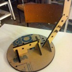
In the time since I designed my timelapse camera gimbal, I’ve laid everything out for laser cutting, researched companies that offer cutting services, and very carefully decided not to send it out. As an initial draft, I wasn’t ready to spend $150 on a process that I’ve never used before.


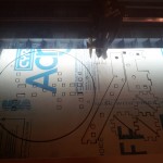
Fortunately, the excellent Laser Cutter Cafe recently started up on a temporary basis. The deal is, you can come in, take a brief training course, and rent time on a laser cutter. Compare to online services, this is relatively inexpensive, and you can cut smaller test pieces and see the results immediately. For rapid prototyping, this is a valuable learning tool.

At the beginning, I was finding that many of my designs had fairly glaring errors that weren’t apparent until I was holding a physical copy. Throughout the process though, I was constantly tweaking and updating the design, and now I’ve got an excellent handle on what works and how everything will fit together.

The tweaking process involved adding, removing, and moving pieces around to fit better. Initially, everything was going to be glued together, but with a combination of finger joints and mortises, most of the individual components slot together and can almost friction fit. Naturally, glue will still be used, but the assembly of the final product is nearly idiot-proof now.


If I were to print this again, I’d arrange the shapes closer, merging the the coincident lines to save on laser-time, but that wasn’t a priority while printing up the prototype.


Relapse

While I’ve been waiting for parts to arrive for Elapse, I’ve decided to build a companion rig that can smoothly pan a camera over the course of hours (or days or weeks or whatever). I’ve nicknamed it Relapse because it’s a repeatable camera gimbal, building on the idea of Elapse.


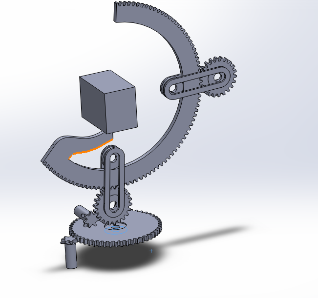
Here’s a quick idea I banged out for Relapse over the course of an evening. This shows the gist of what I’m trying to do, just without any of the structural elements (or gravity).

Prolapse Concept

Those cylinders are stand-ins for some geared motors that I have literally bags full of. That cube in the centre has the same dimensions as my small SLR camera.


After looking around unsuccessfully for cheap gearing that I can source locally, I decided to abandon that and go full-on laser cutter.


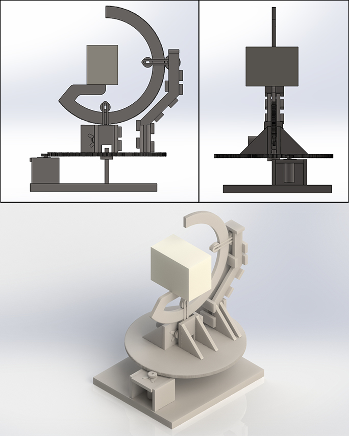
To do that, I had to have pretty exact idea of the dimensions of every piece I’ll need, and how it fits together. That’s a good opportunity to dive deep into Solidworks and make an accurate model of how this thing will end up instead of just a rough mock-up.

After a couple nights’ more of work and a trusty pair of digital calipers, I came up with this:

Final Prolapse Render

Click to make all your wildest dreams come true

Many of the pieces from this (the rails on the sides of the top gear and the bearings attached to them) are measured based off parts that I already have laying around. Using up excess materials is awesome, so that’s always a bonus.

Now I’ve got to pull it apart and lay all the pieces out for a laser cutting template.