
The mechanical design for this project follows the “as quickly and easily as possible” maxim even more so than any other section. I used flat pack laser cut design strategies that results in pieces that snap together. I like that because it could in the future be turned into a kit reasonably easily, and in the meantime, it’s just a quick way to design and iterate.
For this first version, aesthetics plays no part, I just wanted to get the PCB mounted and spinning, along with an appropriate motor.
I used off the shelf mechanical components wherever possible, too. Standard bearings, shafts, collars, and couplers. Oh my.
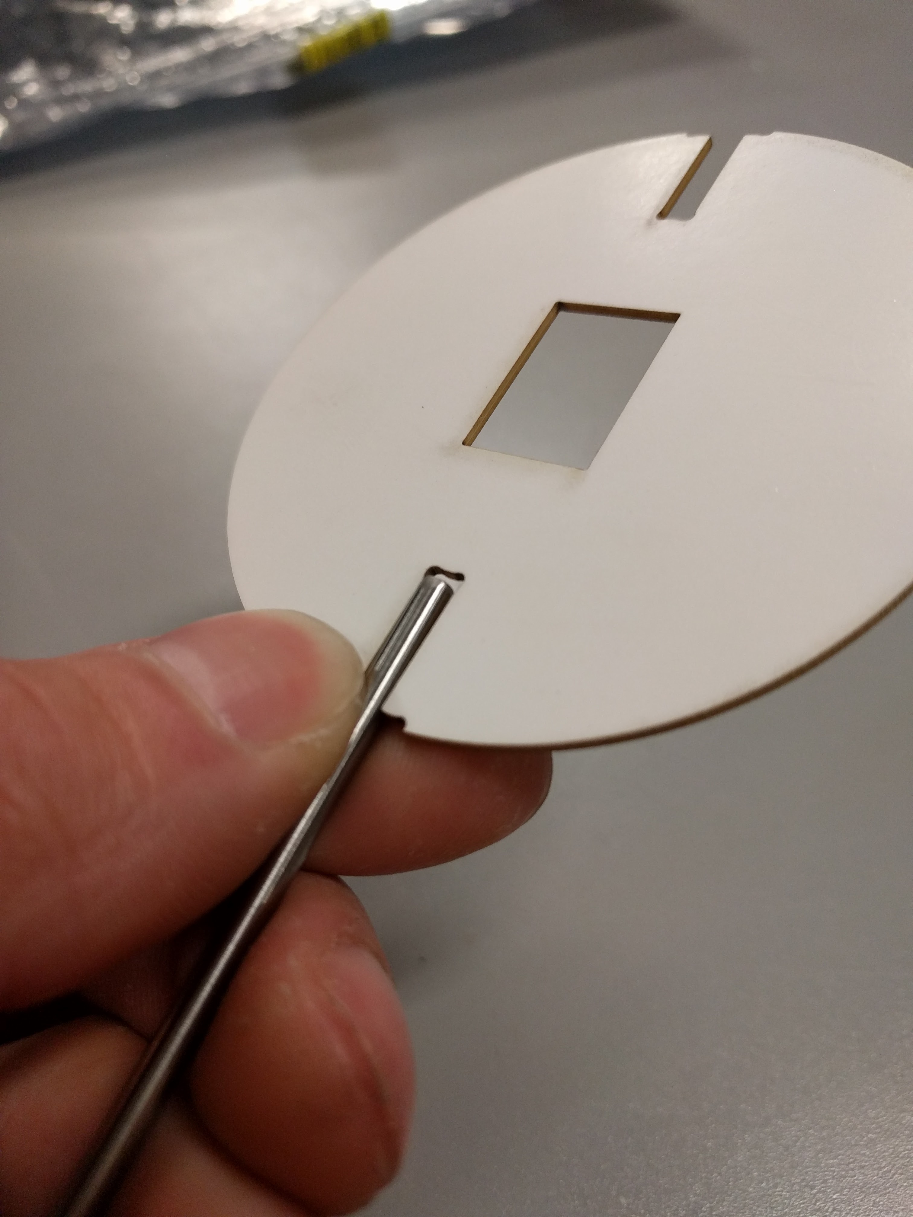
Coupling the PCB to the drive shaft was a challenge that went through a few ideas to keep it manageable. Something off the shelf, or quick and cheap to manufacture. 3D printing is right out. This picture illustrates the problem, along with a laser cut mock up of the PCB:
One of the solutions I explored was to use clevis pins, intended for RC helicopters.
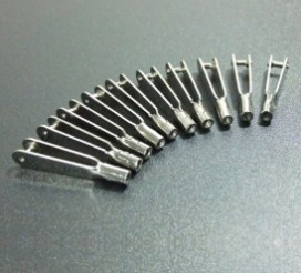
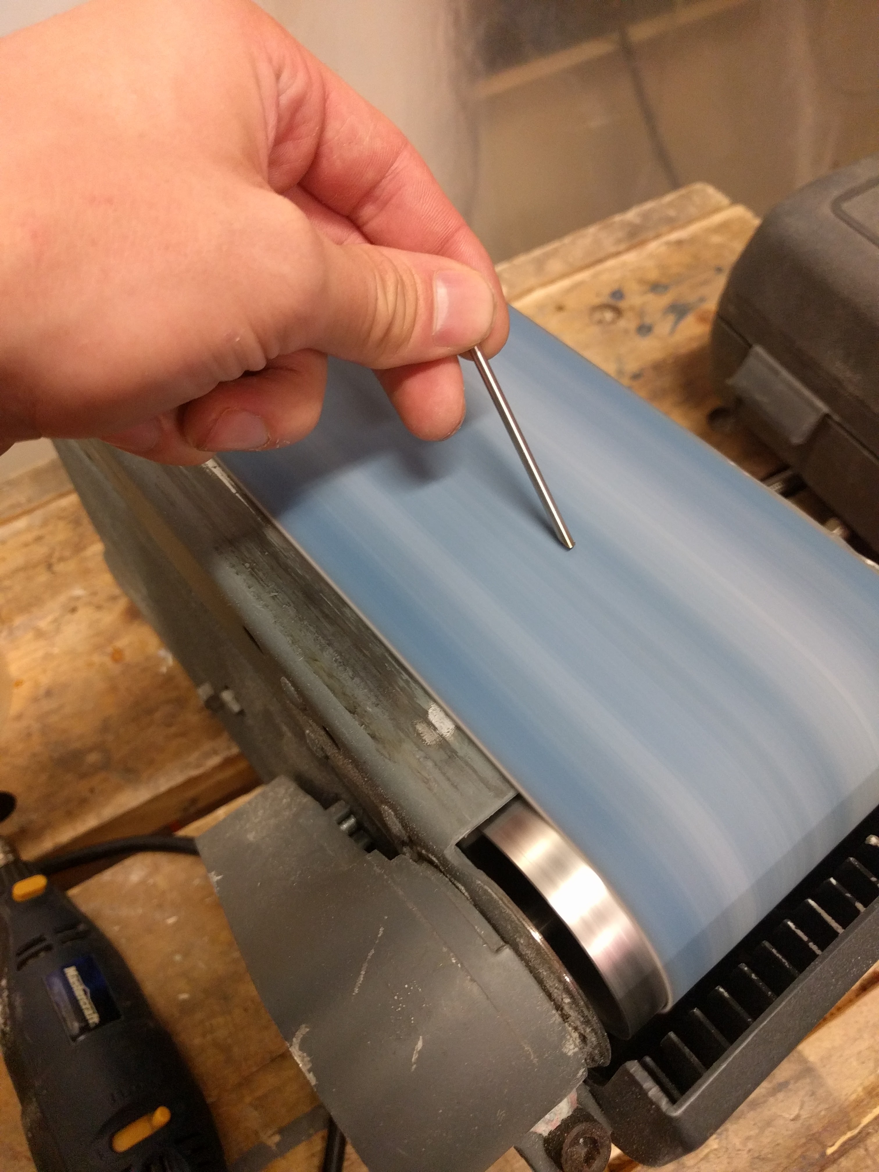
I found some aluminum ones and some nylon ones, but the former ended up being unsuitable for size. The nylon still wasn’t perfect, but here’s a tip for when your shaft is inappropriately large:
You can grind down steel rods to make a serviceable cutting edge, turning it into a poor-but-functional drill bit. Then they’ll drill right into the nylon.


One more issue was battery holding. Ideally, I wanted a cylindrical battery (or batteries) held longitudinally in the centre of the sphere. That seemed best for keeping the spinning disk balanced. For electrical reasons, I chose three LR44 coin cells stacked up to make 4.5v nominally.
After much fruitless battery holder searching, I grabbed a 12mm ID acrylic tube, and cut away part of it such that it could be fit into the PCB and then twisted to lock it in place. Like so:

That actually locked together pretty solidly, and I added a battery spring to the PCB to hold the batteries together.
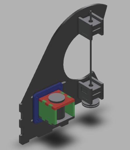
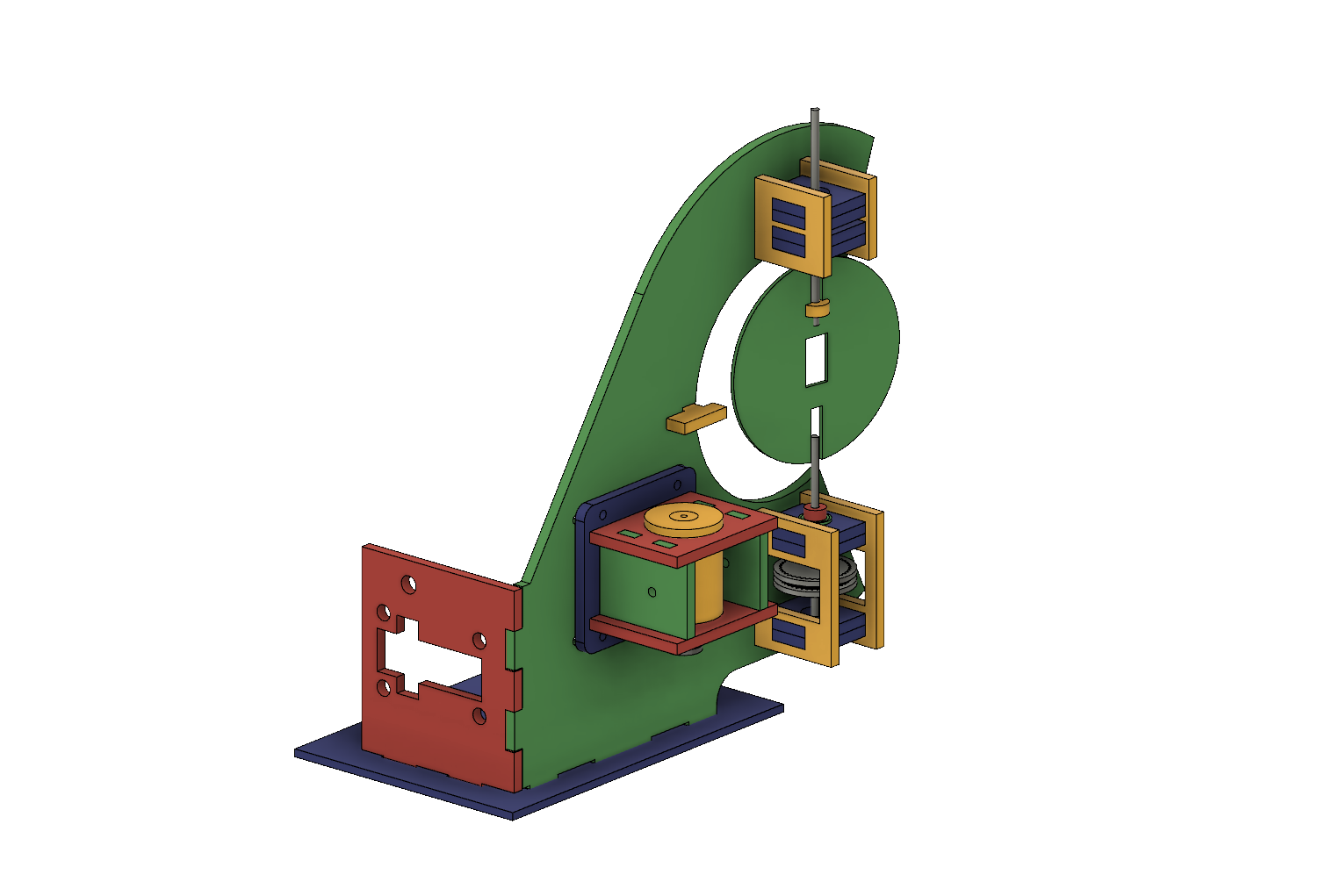
For the overall frame, I tossed something together in Fusion 360:
With the very first cutting, made from totally scrap laser material – mostly acrylic, but some plywood in there for good measure – I found a minor setback: I had the wrong belt size.
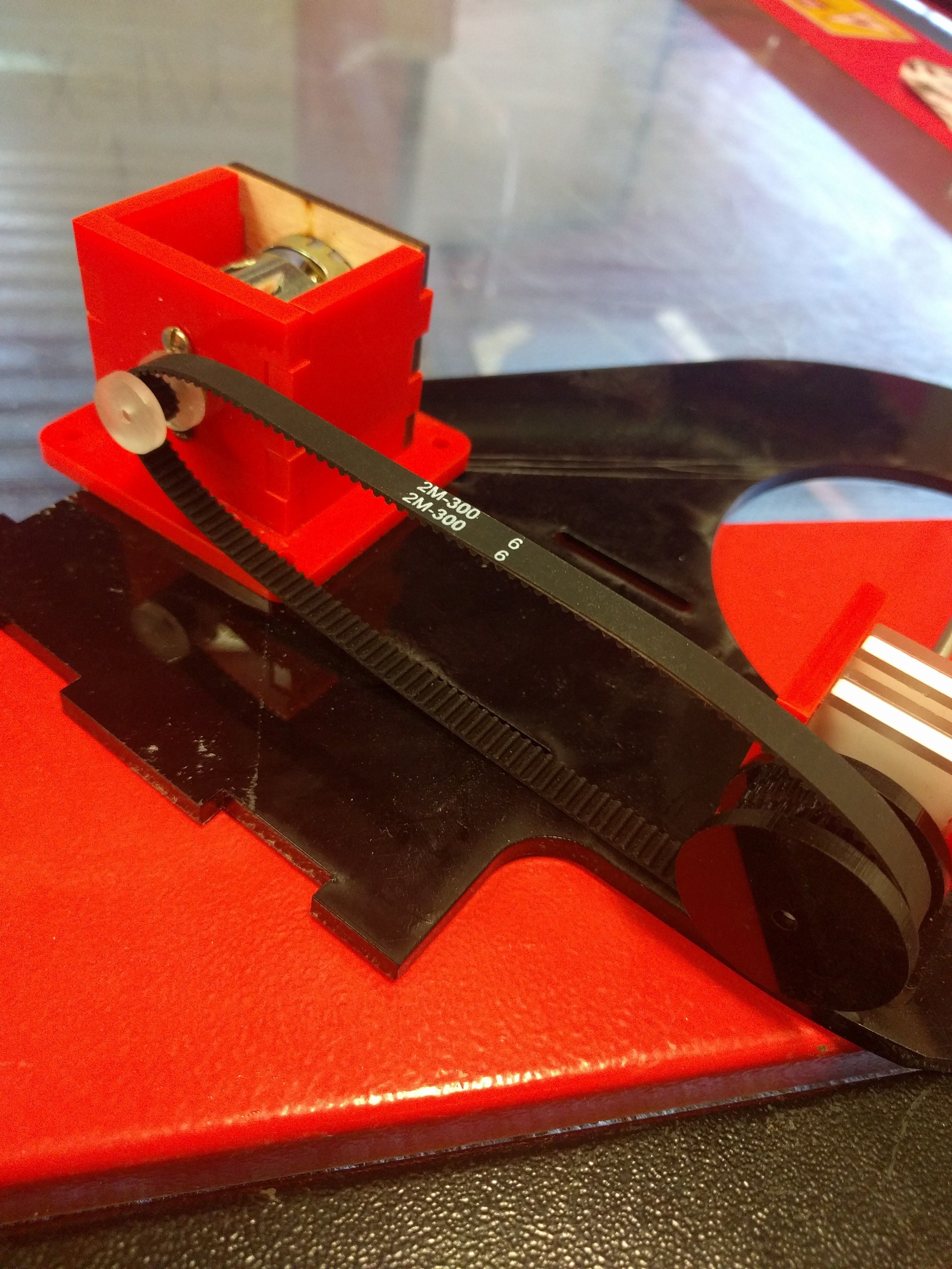
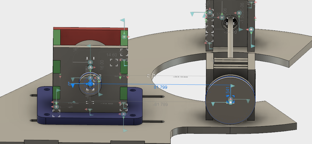
I’m not sure if I calculated wrong the first time, or did some redesigns after purchasing my belt or what, but a second calculation did confirm that my on-paper expectations should have matched my physical fit. I had a 300mm belt, but 82mm between centres at the middle of the adjustment distance, so there was no way that was going to fit.
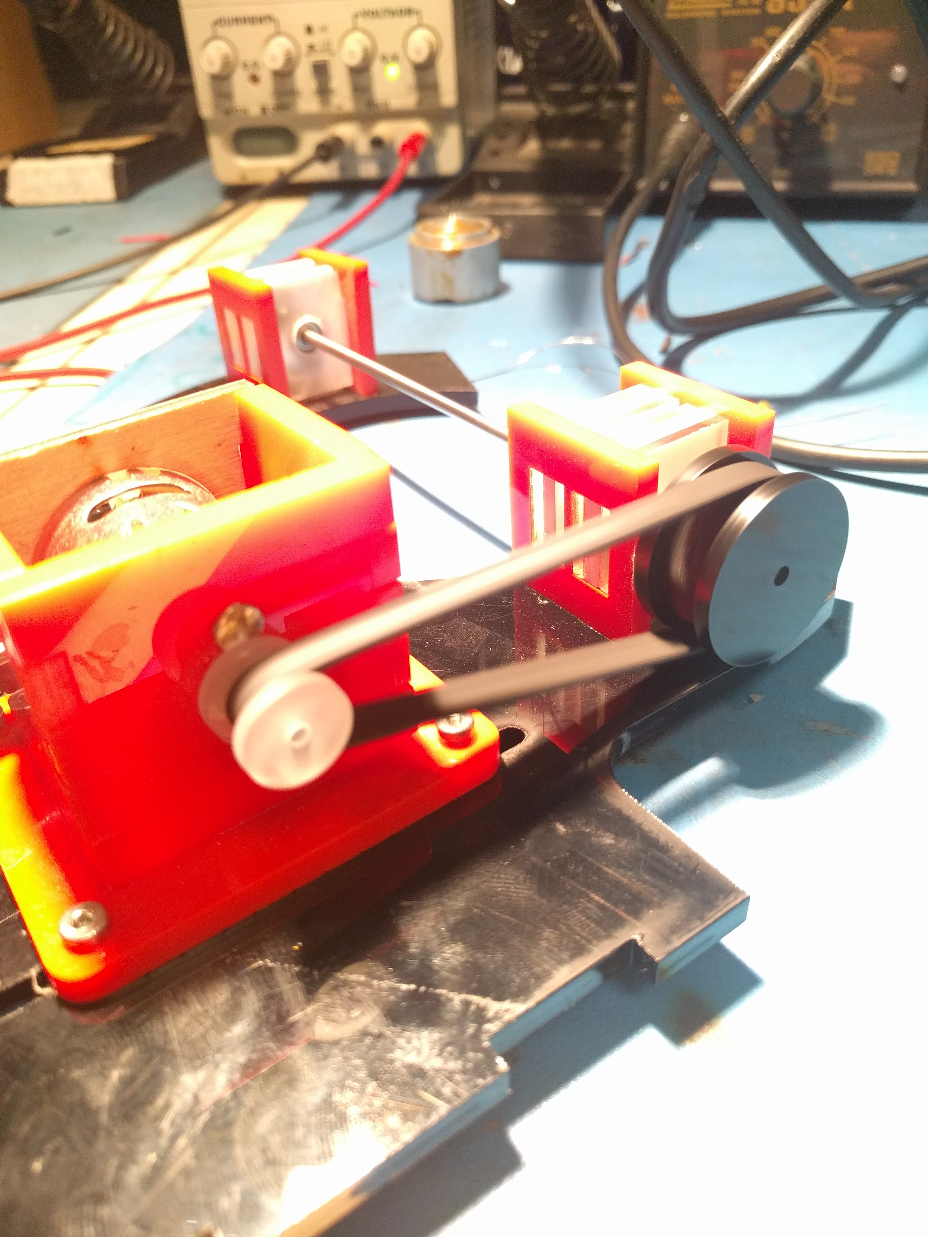
A 200mm belt proved much more suitable and revealed the next issue, which I vaguely suspected would crop up.
First of all, the system worked. Laser cut pulleys work great, I’ve used them before on other projects, and my tension and belt driven design seemed good.
When that main shaft got split and attached to my PCB mock up, however, the shaft was no longer properly supported.
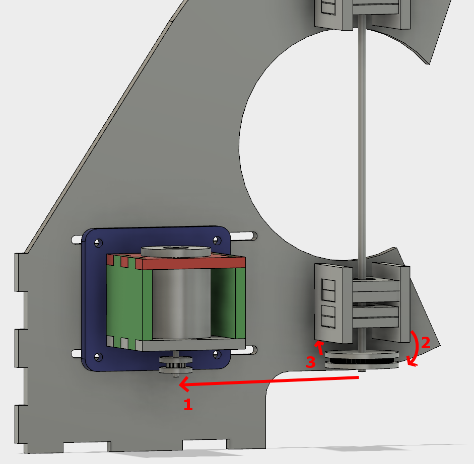
The belt put leftwards force on the shaft (1), causing it to cantilever in that direction (2), and then cause the pulley to rub against the bearing block (3).
I was hoping that the two bearings above the belt would fully constrain the system, but alas, there is too much flex in the shaft or slop in the cheap bearings, with not enough distance in between them.
So, version two. This time with a supported shaft on either side of the driven pulley. I was trying to avoid that because the design and assembly both get a little more complicated.
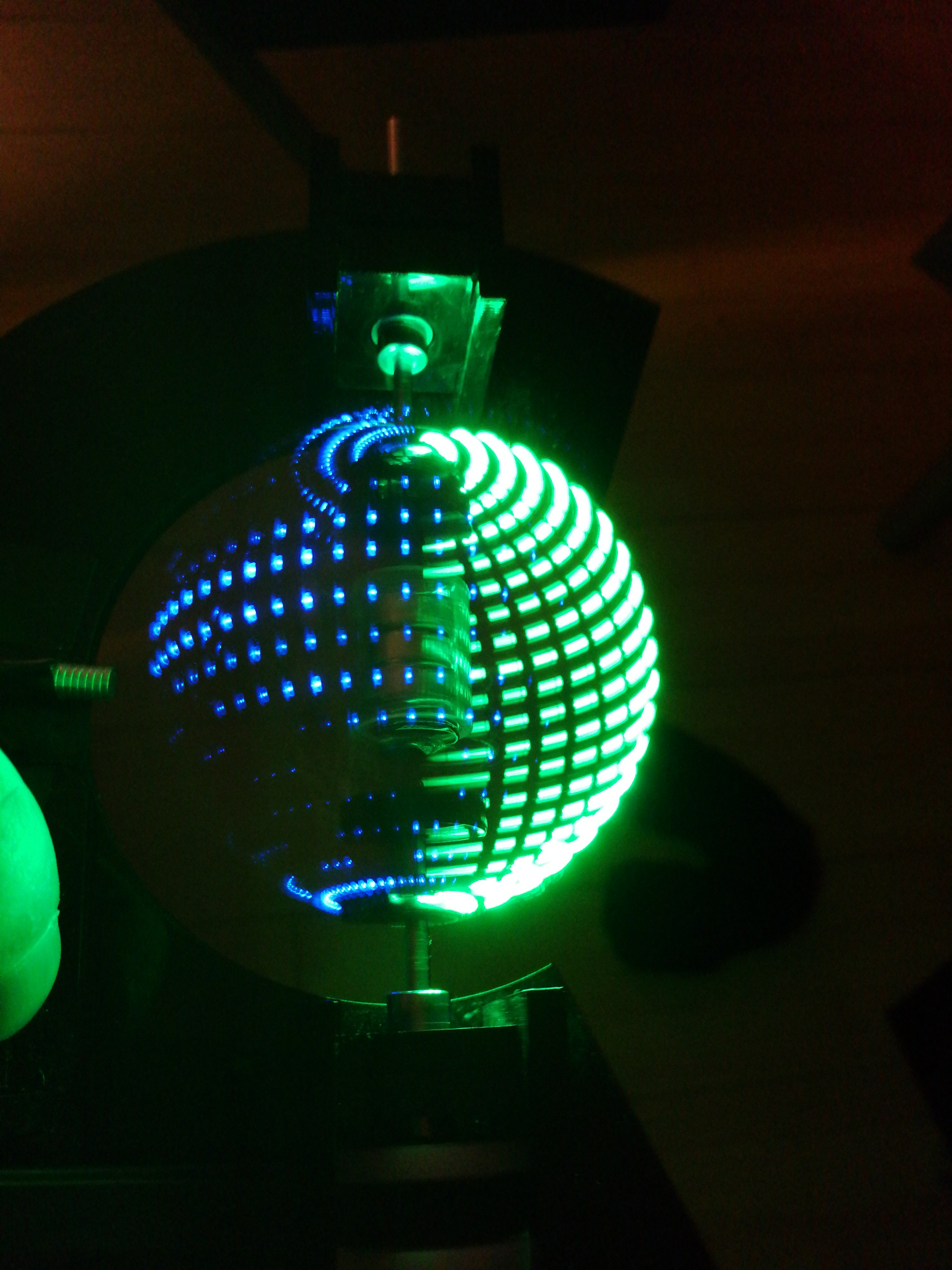
One more change was getting rid of the clevis pins. They rattled and I didn’t like them. Instead I swapped the smooth shafts out for D-profiled versions, and laser cut a notched circle to couple with the PCB.
After cutting and reassembly, it works great!
No more mechanical changes need to be made for this prototype to demonstrate that it works. Next section!