Instead of a TV at home, I use a projector. It’s on my ceiling, with the buttons inaccessible. The remote for it also isn’t really working anymore. Problem.
There’s nothing on the remote control’s PCB except for an obscure microcontroller (TTR013), IR LED and driving transistors, and some carbon contacts for the buttons. The intermittent operation is not the contacts deteriorating, and the microcontroller is getting power, so troubleshooting opportunities are limited.
But, the internet is a wonderful place, and someone has just straight up recorded the exact remote control I need and posted it up on Github.
The config file is here, but they also have the raw recordings. Apparently it’s a config file for a Linux IR transmitter driver called LIRC. The config documentation is here.
It’s pretty straightforward, so I set out to duplicate the waveform using the RMT peripheral of the ESP32. The RMT peripheral is an arbitrary waveform generator, and one of the typical use-cases is an IR transmitter. Perfect.
My final code is here. The From my reading of the LIRC docs, the relevant config data is this:
header 9077 4504
one 602 1622
zero 602 511
ptrail 604
gap 108167

begin codes
ON 0x000CF20D
Where a binary 1 is denoted by an on-pulse of 602 microseconds and then an off-pulse of 1622 microseconds. Similarly for 0, it’s 602-on and 511-off.
The code for ON uses that sequence to write out 0x000CF20D.
The whole packet starts with the header sequence (9077-on, 4504-off) then 0x000CF20D, then the tail/gap sequence (604-on, 108167-off). Seems straightforward.
I put the ESP32 on an oscilloscope to make sure the RMT was doing what I wanted it to do.
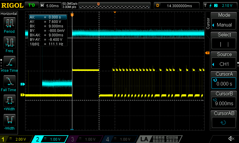
It seems to be! But this is more of a logic analyser task, so I pulled that out. The waveform looked exactly as I expected, so I tested it out with an IR LED.
And it didn’t work at all. Nuts.
By connecting the remote control to the logic analyser and powering it with a nice bench power supply, I was sometimes able to get output data. Enough to grab a capture after several minutes of mashing the carbon contacts with a brass standoff.
Here’s the full waveform:
It’s worth noting that the waveform is inverted from the actual LED current, due to measuring at the LED with low-side switching. Don’t worry about it too much, just invert the logic.
Sigrok can export the waveform in a Value Change Dump format, which looked good enough for my purposes. Then I wrote a python script to convert VCD files into the RMT packet format.
It looked good, with the exception of some glitches caused by the RMT not being able to handle very long delays, relative to the fast switching. This strategy still didn’t work on my project.
Speaking of fast switching, let’s investigate that further. Abandoning the Github config files so quickly didn’t sit quite right with me. It was too perfect.
Going back to my capture of the remote, here’s a binary 1:
Here’s a 0:
And then here’s the header, along with the data portion:
And the header with the whole data portion:
It does look right. But why was this so different from the Github repo?
Well, obviously this has a carrier wave that I totally blew by.

Wow, okay. Back to the LIRC documentation. There is a frequency option that specifies carrier wave, and defaults to 38kHz. So, it’s not in the config, because it’s set by default, and is one line in the documentation. No wonder I missed it.
Honestly, my brutish Python script that specifies all of changing values is probably good enough, but it feels wrong to use a 1500-line lookup table instead of a fixed carrier frequency and 15 lines of actual data. The RMT peripheral made it incredibly easy to fix up.
The end result looks really good, but let’s compare with the captured data again.
Keeping in mind that the data to be sent is 0x000CF20D, I’ve annotated the capture:
And it looks mostly good, except… What’s that block at the end?
I can’t find anything in the original config or documentation for the config that would explain that last block. That will remain a mystery for now.
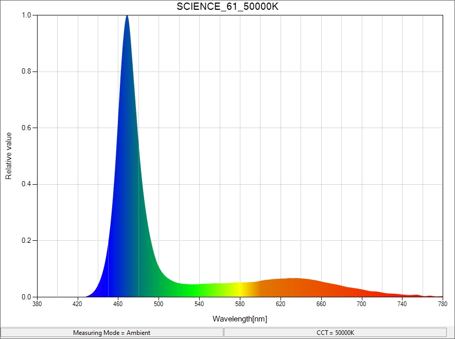
Anyway, it was about this time that I got suspicious of the ancient IR LEDs that were in my parts bin. If I cranked the current, they looked visibly blue, which, obviously is the wrong side of the spectrum when I’m looking for IR LEDs. I grabbed a spectrometer and measured it – Yep, that’s not right.
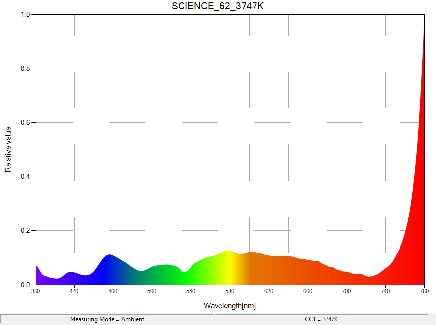
After combing through my parts bin, I found another IR LED and measured it: 815nm. Still not right. I was fortunately able to juuust barely be able to measure the wavelength, though.
Looks like a very broad band 815nm, if the peak stretches all the way to 750nm.
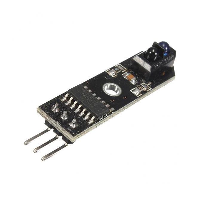
I’m pretty sure I’m looking for a 940nm LED, so some more combing and I found an IR proximity sensor. I don’t have a datasheet, but pointing a TV remote at it triggered the on-board red LED, so I knew it was simpatico.
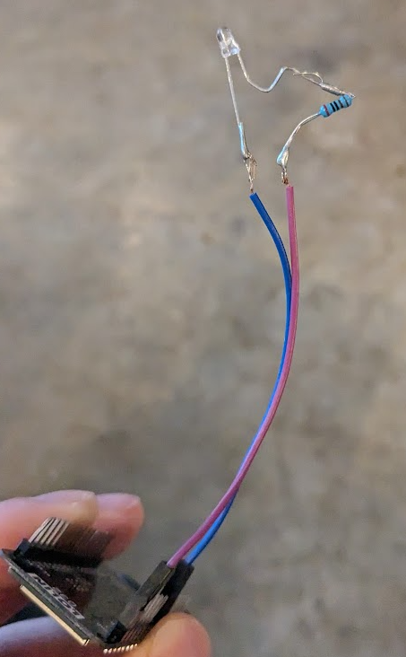
A quick hack-job later, and I drove the LED directly from the ESP32. My projector turned on, without any further changes to my code. And it successfully turned off the projector, too.
So that’s how I controlled my home entertainment setup with an IR proximity sensor.
Sometime in the middle of this journey, I hooked up the LA to a little 315MHz receiver module and triggered my garage door remote. I won’t be posting the waveforms here, but minor modifications to my Python script and code worked out of the box to clone the remote. That whole process took about 15 minutes, so it was a nice and useful diversion. Because it’s attached to an ESP32, I can now trigger my garage door over the internet. From anywhere in the world! Very, very remotely.
This whole project is very specific to my needs, but it could be helpful to others. There is now a pipeline for converting LIRC config files into ESP32 RMT outputs. I doubt I’ll ever do this again, but, just for giggles, here’s a GPT-assisted script that will do it:
This file contains hidden or bidirectional Unicode text that may be interpreted or compiled differently than what appears below. To review, open the file in an editor that reveals hidden Unicode characters.
Learn more about bidirectional Unicode characters
| import re | |
| import argparse | |
| class LIRCConfigParser: | |
| def __init__(self, file_path): | |
| self.file_path = file_path | |
| self.config = {} | |
| self.header = None | |
| self.one = None | |
| self.zero = None | |
| self.ptrail = None | |
| self.gap = None | |
| self._parse_file() | |
| def _parse_file(self): | |
| with open(self.file_path, 'r') as file: | |
| content = file.read() | |
| self._parse_timing_parameters(content) | |
| remote_blocks = re.findall(r'begin remote(.*?)end remote', content, re.DOTALL) | |
| for block in remote_blocks: | |
| remote_name = re.search(r'name\s+(\S+)', block) | |
| if remote_name: | |
| remote_name = remote_name.group(1) | |
| self.config[remote_name] = self._parse_remote_block(block) | |
| def _parse_timing_parameters(self, content): | |
| header = re.search(r'header\s+(\d+)\s+(\d+)', content) | |
| if header: | |
| self.header = (int(header.group(1)), int(header.group(2))) | |
| one = re.search(r'one\s+(\d+)\s+(\d+)', content) | |
| if one: | |
| self.one = (int(one.group(1)), int(one.group(2))) | |
| zero = re.search(r'zero\s+(\d+)\s+(\d+)', content) | |
| if zero: | |
| self.zero = (int(zero.group(1)), int(zero.group(2))) | |
| ptrail = re.search(r'ptrail\s+(\d+)', content) | |
| if ptrail: | |
| self.ptrail = int(ptrail.group(1)) | |
| gap = re.search(r'gap\s+(\d+)', content) | |
| if gap: | |
| self.gap = int(gap.group(1)) | |
| def _parse_remote_block(self, block): | |
| remote_config = {} | |
| lines = block.splitlines() | |
| key_section = False | |
| for line in lines: | |
| line = line.strip() | |
| if line.startswith('begin codes'): | |
| key_section = True | |
| remote_config['codes'] = {} | |
| elif line.startswith('end codes'): | |
| key_section = False | |
| elif key_section: | |
| parts = line.split() | |
| if len(parts) == 2: | |
| key, value = parts | |
| remote_config['codes'][key] = value | |
| else: | |
| if ' ' in line: | |
| key, value = line.split(None, 1) | |
| remote_config[key] = value | |
| return remote_config | |
| def get_config(self): | |
| return self.config | |
| def get_remote_names(self): | |
| return list(self.config.keys()) | |
| def get_remote(self, remote_name): | |
| return self.config.get(remote_name, None) | |
| c_start = ''' | |
| #include <stdio.h> | |
| #include "freertos/FreeRTOS.h" | |
| #include "freertos/task.h" | |
| #include "driver/rmt.h" | |
| #include "driver/gpio.h" | |
| #include "esp_system.h" | |
| #include "esp_log.h" | |
| #define RMT_IO (GPIO_NUM_18) | |
| #define ON_OFF_CONTROL (GPIO_NUM_19) | |
| #define PIN_INDICATOR (GPIO_NUM_5) | |
| static const char* TAG = "ir_transmitter"; | |
| #define RMT_END {{{ 0, 1, 0, 0 }}} | |
| ''' | |
| c_end = '''static void send_on() | |
| { | |
| ESP_ERROR_CHECK(rmt_write_items(RMT_CHANNEL_0, on_key, sizeof(on_key) / sizeof(on_key[0]), true)); | |
| vTaskDelay(44/portTICK_RATE_MS); | |
| ESP_ERROR_CHECK(rmt_write_items(RMT_CHANNEL_0, tail_key, sizeof(tail_key) / sizeof(tail_key[0]), true)); | |
| } | |
| static void send_off() | |
| { | |
| //Off needs to be pressed twice | |
| ESP_ERROR_CHECK(rmt_write_items(RMT_CHANNEL_0, off_key, sizeof(off_key) / sizeof(off_key[0]), true)); | |
| vTaskDelay(2000/portTICK_RATE_MS); | |
| ESP_ERROR_CHECK(rmt_write_items(RMT_CHANNEL_0, off_key, sizeof(off_key) / sizeof(off_key[0]), true)); | |
| } | |
| void app_main(void) | |
| { | |
| rmt_config_t config = RMT_DEFAULT_CONFIG_TX(RMT_IO, RMT_CHANNEL_0); | |
| // set count to 1us | |
| config.clk_div = 80; | |
| config.tx_config.carrier_en = true; | |
| config.tx_config.carrier_freq_hz = 38000; | |
| config.tx_config.carrier_duty_percent = 35; | |
| ESP_ERROR_CHECK(rmt_config(&config)); | |
| ESP_ERROR_CHECK(rmt_driver_install(config.channel, 0, 0)); | |
| gpio_set_direction(ON_OFF_CONTROL, GPIO_MODE_INPUT); | |
| gpio_set_pull_mode(ON_OFF_CONTROL, GPIO_PULLUP_ONLY); | |
| gpio_set_direction(PIN_INDICATOR, GPIO_MODE_OUTPUT); | |
| while (1) { | |
| gpio_set_level(PIN_INDICATOR, 1); | |
| if (gpio_get_level(ON_OFF_CONTROL) == 1) { | |
| send_on(); | |
| } else { | |
| send_off(); | |
| } | |
| vTaskDelay(1); | |
| gpio_set_level(PIN_INDICATOR, 0); | |
| vTaskDelay(40/portTICK_RATE_MS); | |
| } | |
| } | |
| ''' | |
| def generate_c_code(config, output_path, timings): | |
| with open(output_path, 'w') as file: | |
| file.write(c_start) | |
| if timings.header and timings.one and timings.zero and timings.ptrail and timings.gap: | |
| file.write(f'#define PACKET_HEADER {{{{ {timings.header[0]}, 1, {timings.header[1]}, 0 }}}}\n') | |
| file.write(f'#define ONE_BIT {{{{ {timings.one[0]}, 1, {timings.one[1]}, 0 }}}}\n') | |
| file.write(f'#define ZERO_BIT {{{{ {timings.zero[0]}, 1, {timings.zero[1]}, 0 }}}}\n') | |
| file.write(f'#define PACKET_TAIL {{{{ {timings.ptrail}, 1, {timings.gap}, 0 }}}}\n\n') | |
| file.write(f'#define PACKET_ZERO_NIBBLE ZERO_BIT,ZERO_BIT,ZERO_BIT,ZERO_BIT\n\n') | |
| for remote_name, remote_config in config.items(): | |
| file.write(f"// Remote: {remote_name}\n") | |
| if 'codes' in remote_config: | |
| for key, value in remote_config['codes'].items(): | |
| file.write(f"//0x{value}\n") | |
| file.write(f"static const rmt_item32_t {key.lower()}_key[] = {{\n") | |
| file.write(f" PACKET_HEADER,\n") | |
| for nibble in [value[i:i+4] for i in range(2, len(value), 4)]: | |
| file.write(f" //{nibble}\n") | |
| for bit in bin(int(nibble, 16))[2:].zfill(4): | |
| if bit == '1': | |
| file.write(f" ONE_BIT,\n") | |
| else: | |
| file.write(f" ZERO_BIT,\n") | |
| file.write(f" PACKET_TAIL,\n") | |
| file.write(f" RMT_END\n") | |
| file.write(f"}};\n\n") | |
| file.write(c_end) | |
| if __name__ == "__main__": | |
| parser = argparse.ArgumentParser(description='Parse LIRC config files and generate a minimal C file.') | |
| parser.add_argument('file_path', nargs='?', default='lircd.conf', help='Path to the LIRC config file') | |
| parser.add_argument('–output', '-o', default='main.c', help='Output C file') | |
| args = parser.parse_args() | |
| lirc_parser = LIRCConfigParser(args.file_path) | |
| config = lirc_parser.get_config() | |
| generate_c_code(config, args.output, lirc_parser) | |
| print(f"Generated C code has been written to {args.output}") |
Run this with python esp32_convert_lirc_to_rmt.py config.conf --output main.c
It will generate a main.c file that should just compile and have the ESP32 happily spitting out valid data.


