
This is a follow up from Infin1D, Rev 0.5, where I threw together a proof of concept in a few hours. This is the one where I spent some actual time on it and built a base that, while still quite rough, can be incrementally improved to arrive at a final product.
This miiight have been the original inspiration I saw, but the video link is unfortunately dead.
Right off the bat, I should mention that PCBWay kindly sponsored the 4 layer PCB for this. In addition to using them for most of my personal stuff, I get more complicated professional boards assembled by them as well. The quality, speed, price, and communication are all better than what I’ve gotten domestically. So I’m genuinely happy to plug them, they rock.
On to it:
I mentioned previously that I’d like to use a scanner sensor instead of the easy line sensor module I had before. That previous module was 128 pixels long, greyscale, and $20, but also well documented, ubiquitous, and easy to use (mechanically and programmatically).
A linear CCD sensor out of a scanner, on the other hand, is almost the complete opposite. It’s huge (107,000 pixels long), poorly documented, electrically hard to control, full RGB, requires external optics, and needs to be mounted to a circuit board. It is also only really available via Taobao, but it is about $7 in singles. Or at least, the one I chose is.
I started by scavenging a bunch of scanners and seeing what was inside. Most of them happened to be the Epson Perfection 1250. I guess it was just an insanely popular scanner.
Searching “Epson Perfection 1250 Service Manual” yields excellent results, so this particular RGB linear CCD is a 22-pin package called ILX555K.
The main processor chip on the PCB is the National (now TI) LM9833, which is a little ridiculous. It contains an analog CCD reader, DRAM storage, high current stepper motor outputs, a USB interface, and even extra helper functions like paper load detect. Basically a single-chip scanner brain.
Initially, I didn’t even have to do any proper hardware hacking (sad day), because there are Linux drivers to talk directly to the chip. It uses something called SANE, an easy Linux scanner interface. SANE is actually a really nice codebase to hack on. Well laid out, clear, and simple.
There are also convenient Python bindings!
First:
sudo apt-get install python-dev libsane-dev sane-utils
git clone https://github.com/python-pillow/Sane
cd Sane python setup.py build
sudo python setup.py install
sudo pip install pillow
sudo pip install numpy
sudo mount --bind /dev/bus /proc/bus
sudo ln -s /sys/kernel/debug/usb/devices /proc/bus/usb/devices
sudo sane-find-scanner
> ...
> (vendor=0x04b8 [EPSON], product=0x010f [EPSON Scanner 010F]) at libusb:001:002
> ...
sudo nano /etc/sane.d/plustek.conf
That file gets modified with the found USB vendor/product/etc info.
And you’re done!
Running scanimage will run the scanner, including homing and making the carriage move, but it doesn’t provide the granularity we need. The source for that provides detail around line 1862, probably calling feed() or reset() / initialise cmd. Sending the initialise byte for a long scanner homing sequence is still pretty high level, so it must be handled within the IC.
That was a fun detour, but ultimately not what I wanted out of the system.
So I threw together a really quick PCB, and I made many mistakes. But that’s okay, that’s what revision 1 is for.
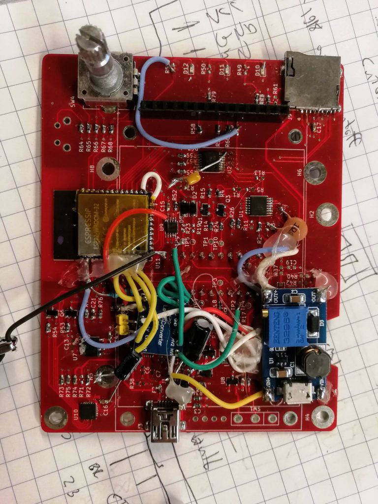
And it works! My initial firmware can display images and I also wrote a bitmap generator to save to the SD card.
A rudimentary interface:

Obviously lots of bodges had to be made. Mostly because of the many voltage rails – the sensor has 5V signaling, while the CCD itself is charged with 12V, the microcontroller is 3.3V, and there’s the whole 5V / battery voltage mess. So this board is more bodge wires and hot glue than PCB at this point.
So how well does it work?
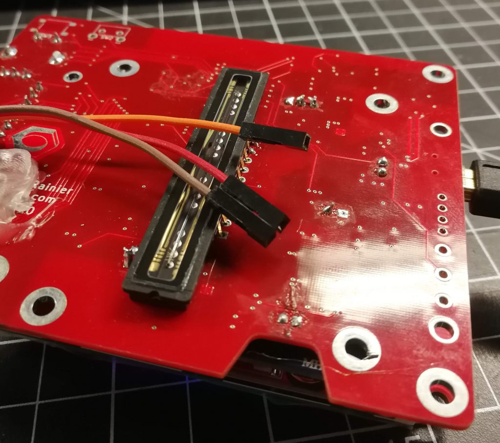
Well, here’s another difference between the original module I used and this sensor: The sensor doesn’t have an integrated lens.
Due to ubiquity, I picked up an M42 camera lens mount for a couple bucks and found a $20 lens on Craigslist. The M42 lens is an old 35mm standard, which is coincidentally just the size of my sensor. Used to be very popular too, so good deals can be had.
However, I have not yet designed a chassis, so anything the image captures will be a blurry mess.
One more issue is that I’m still tweaking the hardware around the analog output. The sensor datasheet recommends feeding its output through the base of a BJT transistor as a sort of transimpedance amplifier. It’s kind of a strange way of doing that, so I’m playing around with proper op amp methods to do that consistently and repeatably. That requires a fair amount more tweaking though, as the datasheet has no information on the nature of the output that is expected. That’s just a matter of putting more time into the investigation, but in the meantime, I have poor dynamic range.
So here’s the first test image that came out of it:
The scan is the red channel only, from left to right. Starting with something dark covering the sensor, and at a very obvious point in time, I removed it and put an object centre of the sensor. I would consider that a success, albeit not as pretty as I’d hoped.
Here’s the object:
In addition to the many above changes, some software updates I’ll write down the line are to integrate better the two obvious viewing modes: waterfall, and histogram. The histogram mode is useful for getting focus right, and then switching over to waterfall mode (as shown above) to see images.
Histograms, similar to the feature that is often available in DSLRs, could show the sensor input intensity as a vertical line on a graph, with pixel position on the horizontal. The steeper the histogram, the sharper the focus.