
This is a fairly old project that I just wanted to document to current-state and provide a conclusion. See here for the old logs.
Some of the original design goals for this project were ease of design, and manufacturabilty. Ideally, the design would be clean and turnkey enough for me to be able to at least sell the populated PCB as part of a kit. I also didn’t want to spend a lot of time doing anything cutting edge enough to turn into a time consuming side project, as some of my designs are wont to do.
So here is where I started.
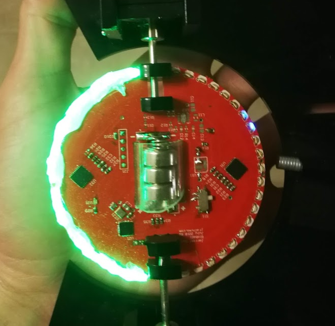
The board is 7cm in diameter with 0805 side-mount LEDs all around the perimeter, green on one side, blue on the other. The LEDs were too easy to see individually (right), so I used hot glue to create a diffusion layer (left).
In the centre, I decided to go the easy route and make the board battery powered. The cutout can hold three LR44 batteries in series.
After some hemming and hawing about how to mount them exactly, I found an acrylic tube with a 12mm ID (just barely larger than the batteries), cut a slope into one side so that it can be inserted into the slot and then rotated to lock in. On the PCB, there is battery spring on one side, and some copper braid on the other to hold the batteries tight and make electrical contact. This solution works better than it has any right to, it is fantastic but blows my “manufacturable” requirement right out of the water.
For driving my LEDs – twenty per semicircle – I used a TLC5947. It’s a constant current, 24 channel PWM LED driver, controlled over SPI(a requirement for speed). There are two of them, and they seemed to work well, with one caveat that I’ll get into in a bit.
There is an interesting power section that I never ended up populating. The goal with it was to have a switch mode power supply attempting to boost the battery voltage to 4 or 4.5v from whatever voltage the batteries sag to. The idea being that with fresh batteries, it wouldn’t be doing much of anything, but as the battery runs down (internal resistance gets higher), the power stage attempts to pull more and more current to keep the output rail steady. The circuit ended up working fine with all of that jumpered over and direct from the battery, but it was an option in case that hadn’t turned out.
I also had a clever system on there to ensure proper polarity to my circuit regardless of how the batteries were hooked up, but again, didn’t matter enough for this version to use.
The TLC5947 has an SPI output pin to allow chaining multiple chips together, but naturally, it would halve the refresh rate I’d be able to get. I ran a trace between the two chips, just in case, but I was also able to avoid using that. The dual effective SPI ports I managed to get working(written about in a previous log) saved me from that.
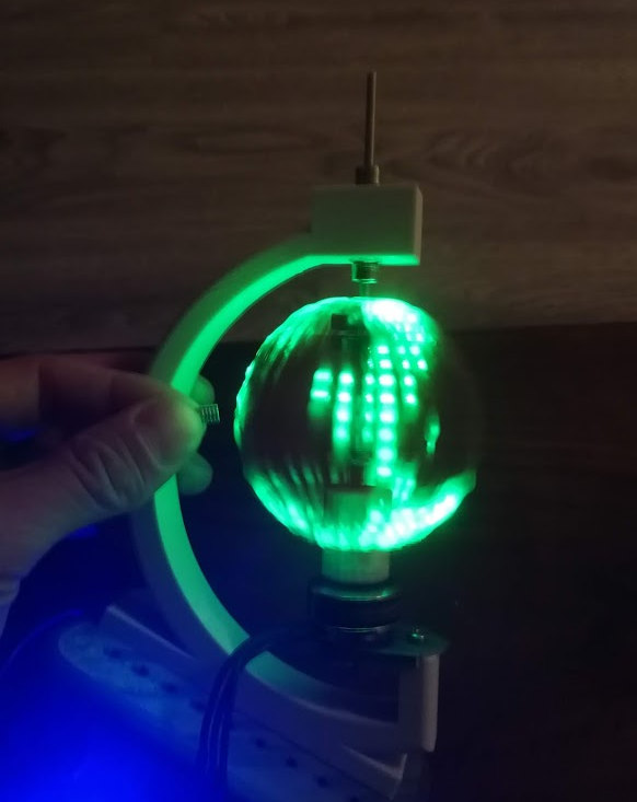
Early tests were promising – I quickly got a recognisable image of the world showing.
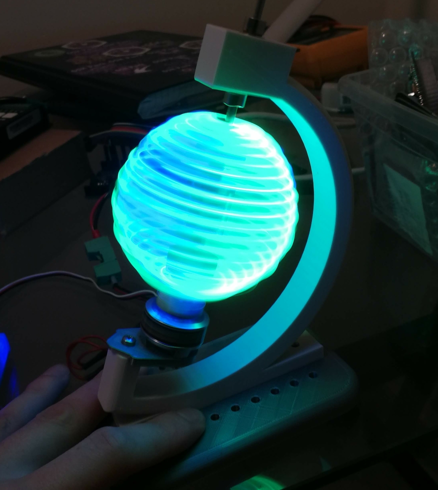
Introducing blue turned it into an unrecognizable mess, though. All further testing stuck to green, for now. The problem is that my hot glue light diffusion is too good, and allows light to be directed back through the sphere. Some sort of baffle on the inner side of the LEDs is needed.
An additional problem that I hinted at in the last logs is that my vertical resolution isn’t really high enough. The world map is recognisable, if you know what you’re looking for, but it isn’t fantastic.
And the final problem, the real deal killer: the TLC5947 blanks its output before displaying the next value. That is, a channel displaying 255 (full on) when a new value is sent to it, even if the new value is the same. It will go 255->0->255. That’s why you can see vertical gaps in all the images I’ve posted. This is mentioned nowhere in the documentation, and is just poor design. So future version will have to rethink this portion, too.
For the mechanicals, due to an unfortunate move, the old system got a little bit damaged and I 3D printed a replacement. This one also uses a direct drive brushless DC motor instead of the old brushed motor and DC motor. Again, just for fewer components and faster to put together.
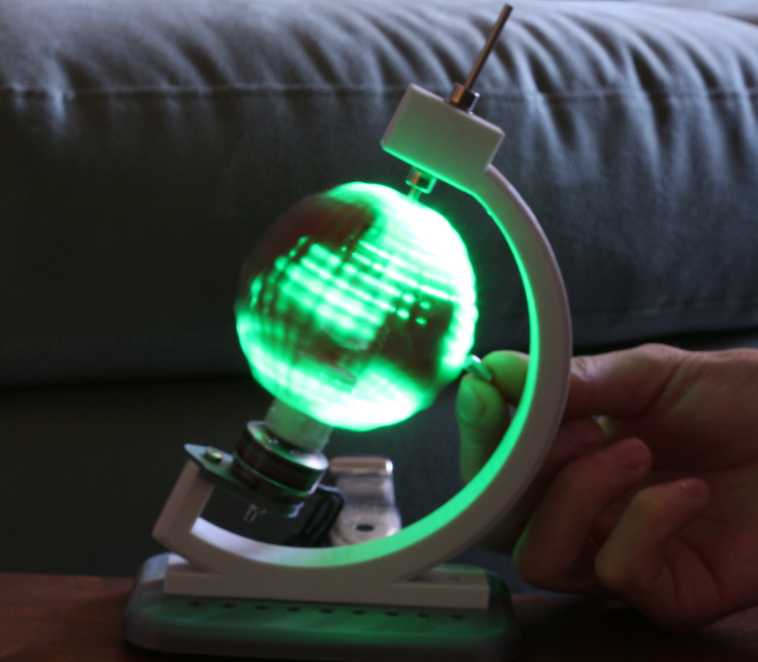
It worked well, other than some harmonics causing a lot of vibrations on some narrow bands of frequency. Future versions would also have a proper magnet holder, my hand is not a permanent solution.