
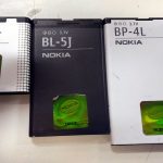
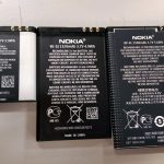
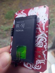
I have access to a big box of Nokia phone batteries. This is a problem. It is very large. I do not have enough Nokia phones to use them all.
There are three sizes:
BP-6MT (1050mAh), BL-5J (1320mAh), and BP-4L (1500mAh).
After some catalog-hunting (be vewwy vewwy quiet), I’ve found the connector they use, the A117827CT-ND.
Update: This handy website has sizes of various batteries listed.
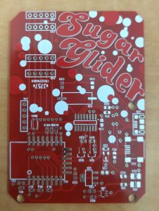
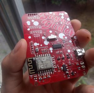
This PCB – I call it “Sugar Glider” – is a battery-powered ESP8266 wifi module. It supports charging a single LiPoly/Li-Ion battery over USB, running off the battery, or both while it’s plugged into your choice of MicroUSB or Mini USB connector.
Mostly using the reference design of the MCP73831 charger chip, and it powers an ESP8266. There is also a CH340G USB-serial chip for programming, so it basically acts like a NodeMCU.
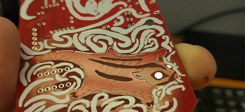
But wait, there’s more! Despite the simplicity of the design, and really not caring that much about it, it took a tonne of time. That’s because I’m rusty at drawing from not having done any in the last decade, and it looks like this!
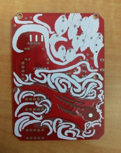
This was done by exporting gerbers, converting each layer to B&W images, then loading them up in my (also decade old) copy of Photoshop. They were coloured according to my sampled colour palette, and then drawing commenced.
When I was done, they were loaded back into CircuitMaker using the techniques detailed here and here. I think I’ll try to do more of this in the future. Having this much unused PCB space is rare, though – It was needed to act as a sled for the batteries, so it’s quite large. Usually I make boards as small as reasonably possible to save on costs.
The assembly went reasonably smoothly. You have a choice of populating the micro- or mini-USB connections. I prefer the mini, because there are something like 20 different possible microUSB connector footprints. In future versions, I’ll probably also use a 0-ohm resistor to select which one. Having an unpopulated connector on the same line is a recipe for bad signal integrity and unwanted antennas.
The power supply portion of this is simply a low-drop out (LDO) linear regulator, because I wanted to bang this circuit out quickly without having to design a switch-mode power supply (or: the Right way to do this project). Slight problem: the LDOs I sourced from China, well, weren’t very LDO. They had a full volt drop across them, leading to 2.7v seen on the ESP8266 at nominal battery voltage. No bueno.
The solution is very simple; just replace the regulator with a proper part from Digikey, that comes with a datasheet. Modern ones are usually closer to 0.2v. That’s the stuff.
This project was created in CircuitMaker. Here’s a link the cloud project page, but here is a zip file of all the relevant files – Schematics, PCBs, gerbers, and layer drawings. The resource-heavy images don’t play nicely with PCB design, so I recommend deleting them while editing the PCB, and then adding them back in right before export.