Archive for January 21, 2015

FFChkMate

I’ve posted here before about my troubles with flexible flat connectors. Well, not directly, but that always seems to be a tangential obstacle in the already perilous minefield of hardware hacking.
Basically, I hate them and I want them to go away.

The answer is, obviously, a breakout board, but I was having trouble finding exactly what I wanted. The system that I was having trouble with is 0.14mm pitch, and an odd number of pins. That means that the connector’s pins are staggered instead of directly across from one another. Slightly unusual, and I couldn’t find an inexpensive breakout board for it.

Over an evening, I started designing a board that should help. The idea is to keep a few of these boards on hand, and if you’re working with an FFC cable with a pitch of 0.14mm, toss an extra cable and a couple connectors onto your next Digikey order. Should run you a couple bucks.

In choosing what kind of connectors I wanted the board to support, I had some decisions to make. Odd or even pins? How many?

I solved those by parsing Digikey’s catalogue:

FFC Chart


A general theory is that the more connectors of a certain pin count in the catalogue, the more common it is in the wild. As shown, it’s definitely important to support more than 30 pins. There’s another big spike at each common count, ending at about 51. That settled that.

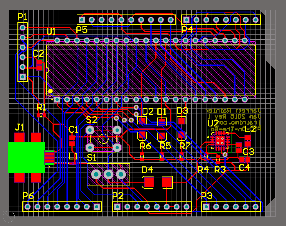
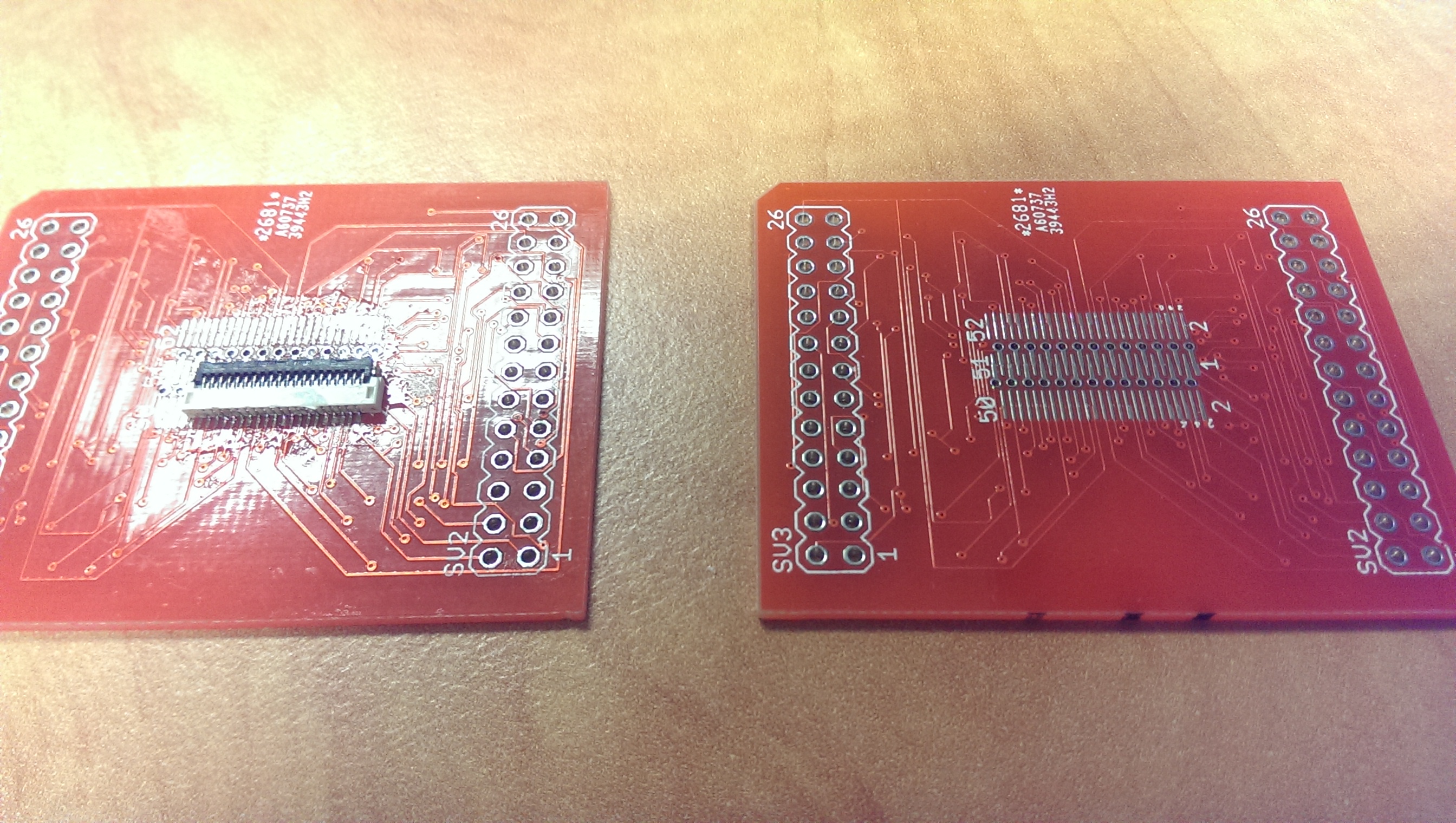
There was another clever idea involved: the centre of the board is a flat cable connector footprint, with a little bit of a tweak. The middle row of pads correspond to pin 1, and every second pin after that. Depending on whether your connector has an even or odd pin count, you use the outer row of pads that are in-line or staggered, respectively. Those all break out to the pin headers as shown on the silkscreen.
There’s your breakout. If you need your cables connected to the device under test, use two boards, solder female header pins on one, male on the other, and sandwich them together, both connectors on either the inside or the outside as shown.

Obviously this may cause issues with length-matched traces, but you know. Cross your fingers. Worth a shot.

Future goals: Actually draw the traces myself, because the autorouter is terrible. I just wanted to spend as little time on this as possible.


FFChkMate


It seems to work fine, though. I’m not trying to get GHz signal through it or anything.


You can get one through dirtypcbs here, or I’ll release the files when I eventually dig them out and make the traces pretty.

Travel-PIC

With the huge popularity of Arduino in the past few years, everything that can be advertised “Arduino-compatible” is being commoditized to such a huge degree that it can be hard to find price-competitive components that do not have that distinctive Arduino pin layout.


An example is this TFT touchscreen LCD. It’s like, 6 bucks, which is insane. This is definitely going to show up in some future projects of mine.


Having everything work as an Arduino shield is all well and great, but I’m generally against using them. My problem with that whole ecosystem has always been that:

A) It shields(get it?) you from what is really happening on the microcontroller

B) It follows that if the user is unfamiliar with the inner workings of their system, then they will be motivated to leave the entire Arduino in place in their project

Historically, that second point has meant that people will build a project and run it permanently using what amounts to a single $30 microcontroller.

With the above commoditization argument, this point is fast losing ground when you can now buy a Chinese Arduino clone for $3.


Those arguments don’t even make sense anymore! I guess what it boils down to now is that Arduino offends my inner perfectionist.

Microchip PICs are fantastic because they are easy to use, powerful, and extremely inexpensive.

I can find a 60 cent chip that has exactly the peripherals I need, with almost no bloat.

The problem is that I have to build it into a circuit every time, thus negating the cost benefits with a time penalty.


Anyway. I have a whole bunch of PIC18F4520 DIP packages kicking around, and some other similar ones (4431 I think?). I suspect that I will be forced to start using Arduino eventually, but at least with this method I can now do some of my simpler PIC development on-the-go with USB power.

For some reason the TSA doesn’t like it when I try and take a breadboard, wire, and wire strippers onto a plane.

So the result:

A PIC dev board in an Arduino form factor.

PIC-On-The-Go SchematicPIC-On-The-Go Bare BoardPIC-On-The-Go with fill


Powered by USB (no communication, though), switch-selectable 5V/3.3V power rail (don’t hit this while plugged in!), reset button, 3 LEDs, and I’ve tried to match most of the Arduino pins with the associated PIC functions (eg. SPI and analog pins are in the same location).

You still need an external programmer, but that’s okay. Programmers are pretty cheap and come in a sleek form factor. The programming header pins match the Pickit 3’s pinout, so it’s just plug-and-play with MPLAB.


When I get the board and give it a test ride, I’ll release the source files. Altium, though, so many people won’t be able to edit them.