Archive for Globe

POV Globe – Electronics


This is a fairly old project that I just wanted to document to current-state and provide a conclusion. See here for the old logs.

Some of the original design goals for this project were ease of design, and manufacturabilty. Ideally, the design would be clean and turnkey enough for me to be able to at least sell the populated PCB as part of a kit. I also didn’t want to spend a lot of time doing anything cutting edge enough to turn into a time consuming side project, as some of my designs are wont to do.

So here is where I started.
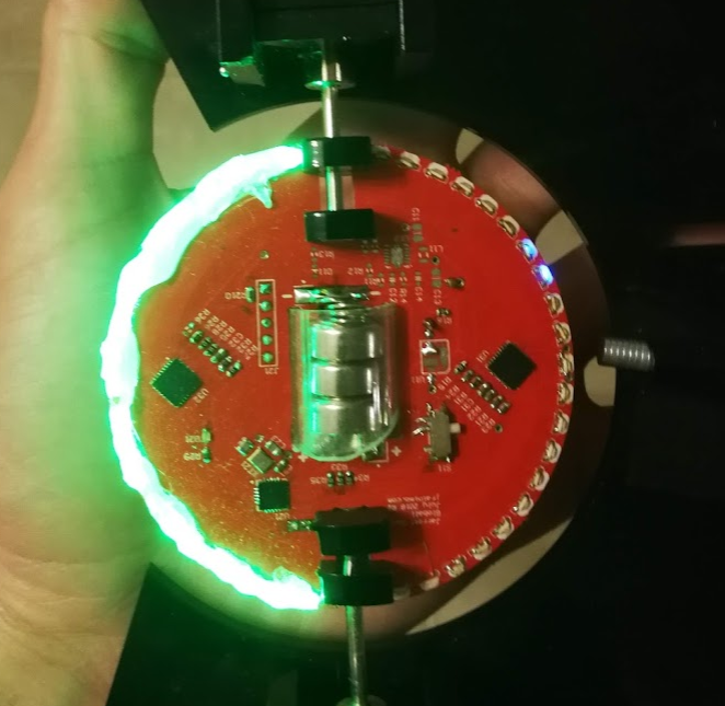
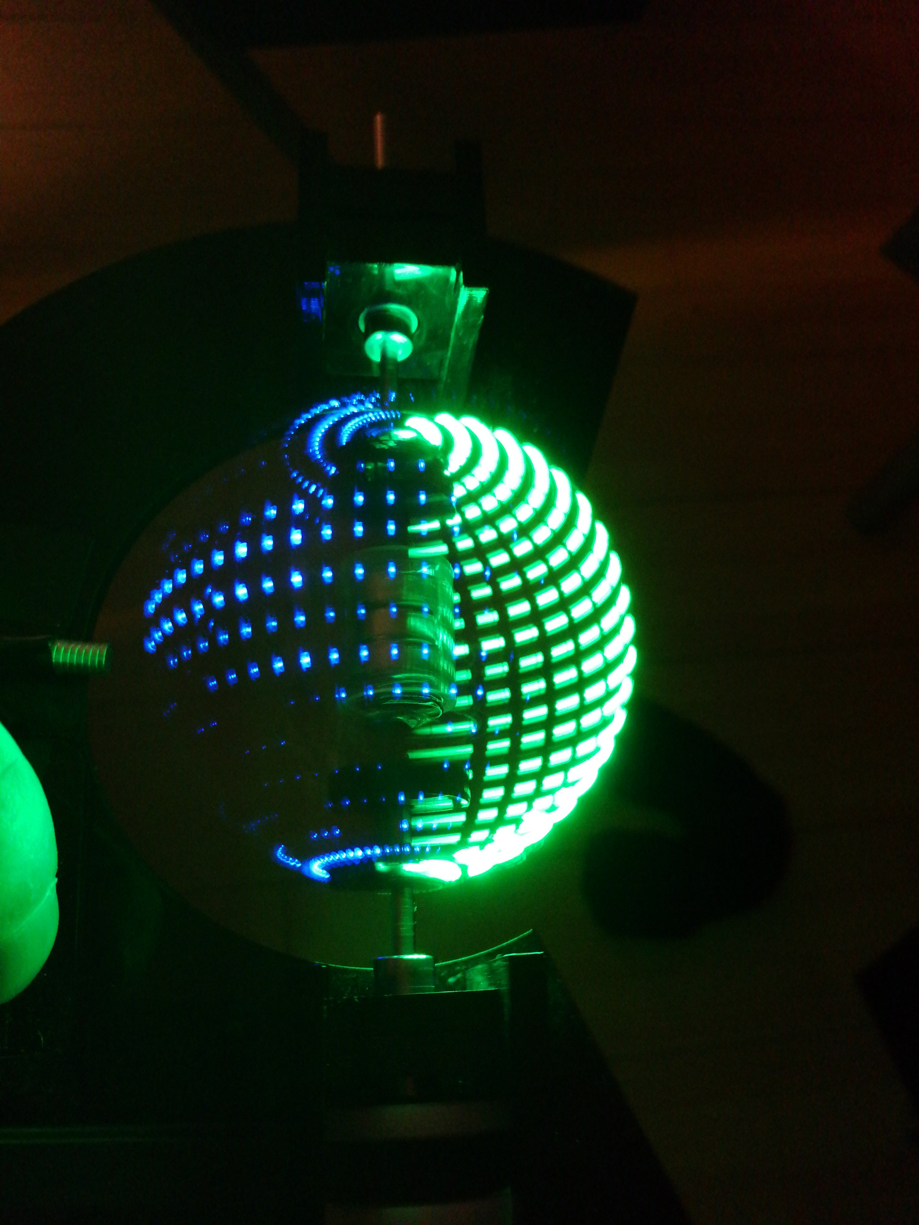
The board is 7cm in diameter with 0805 side-mount LEDs all around the perimeter, green on one side, blue on the other. The LEDs were too easy to see individually (right), so I used hot glue to create a diffusion layer (left).

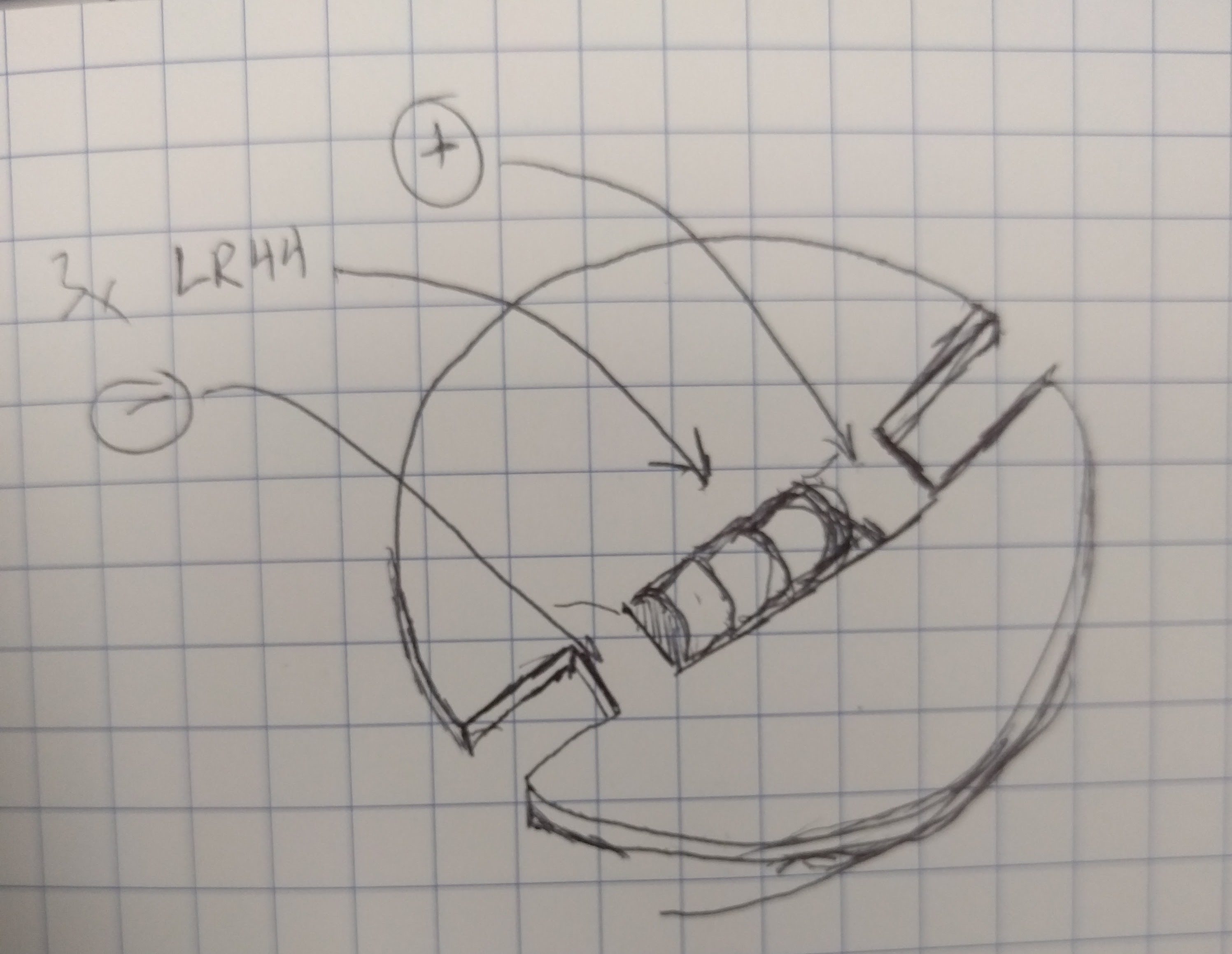
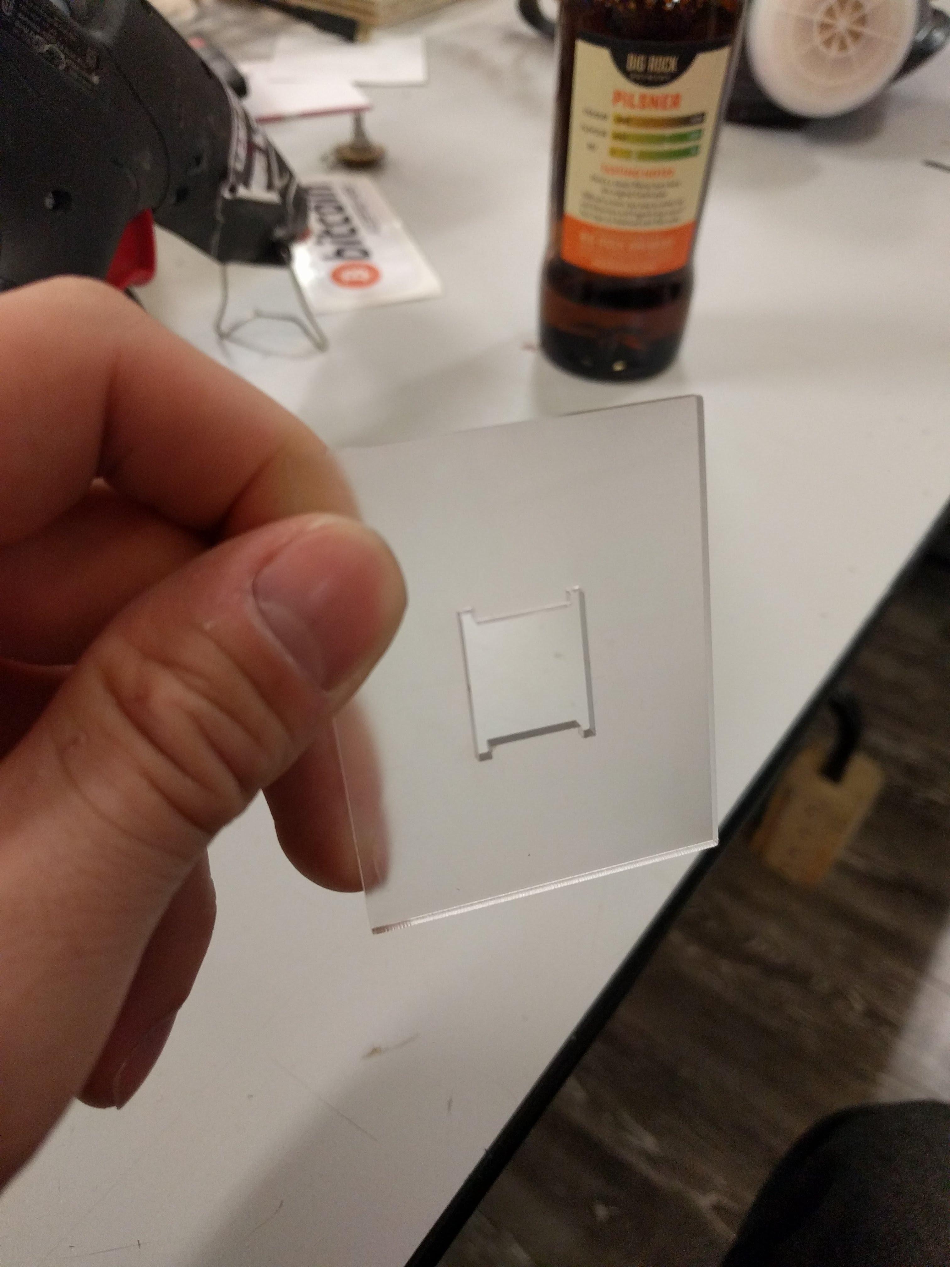
In the centre, I decided to go the easy route and make the board battery powered. The cutout can hold three LR44 batteries in series.

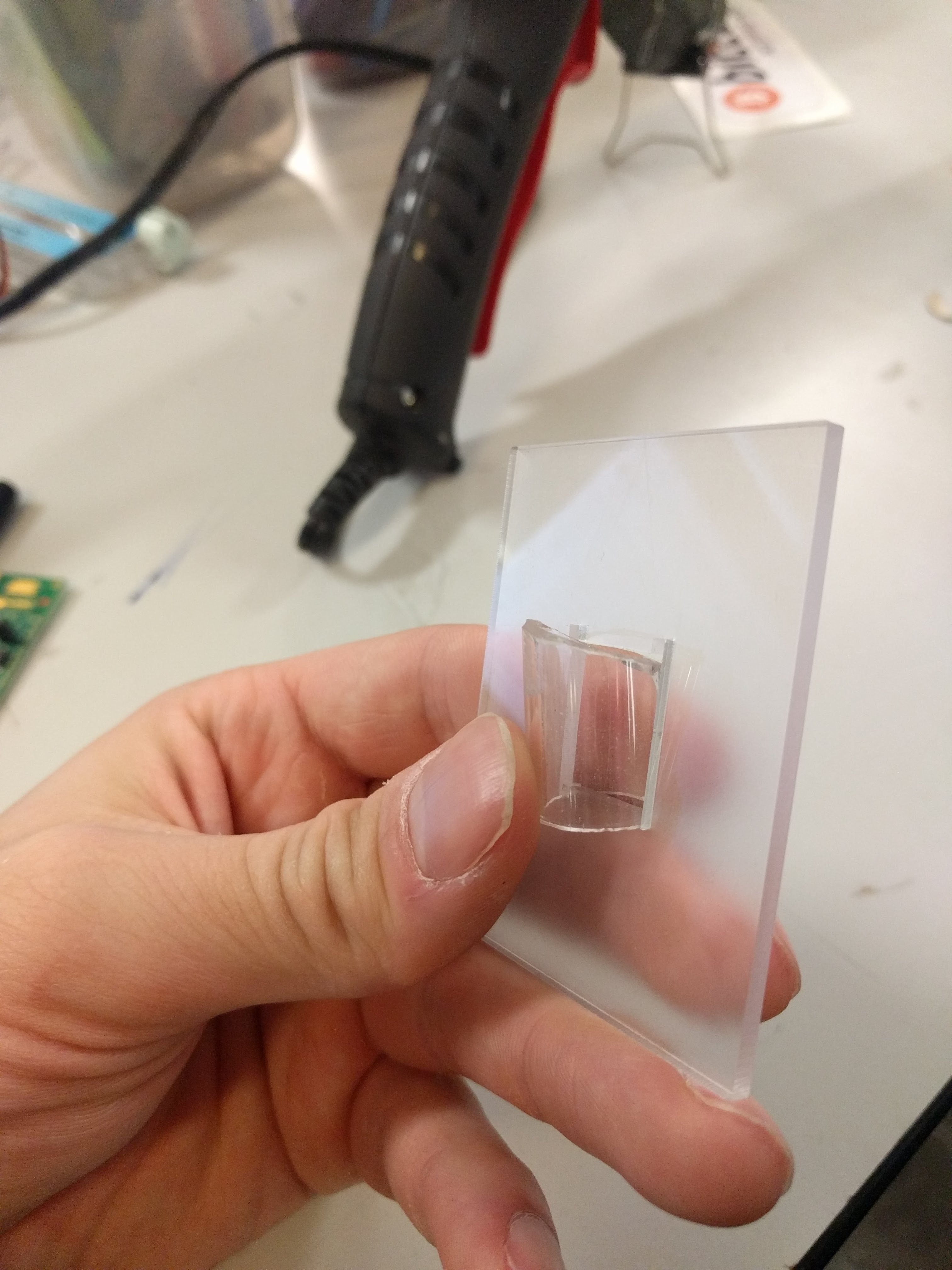
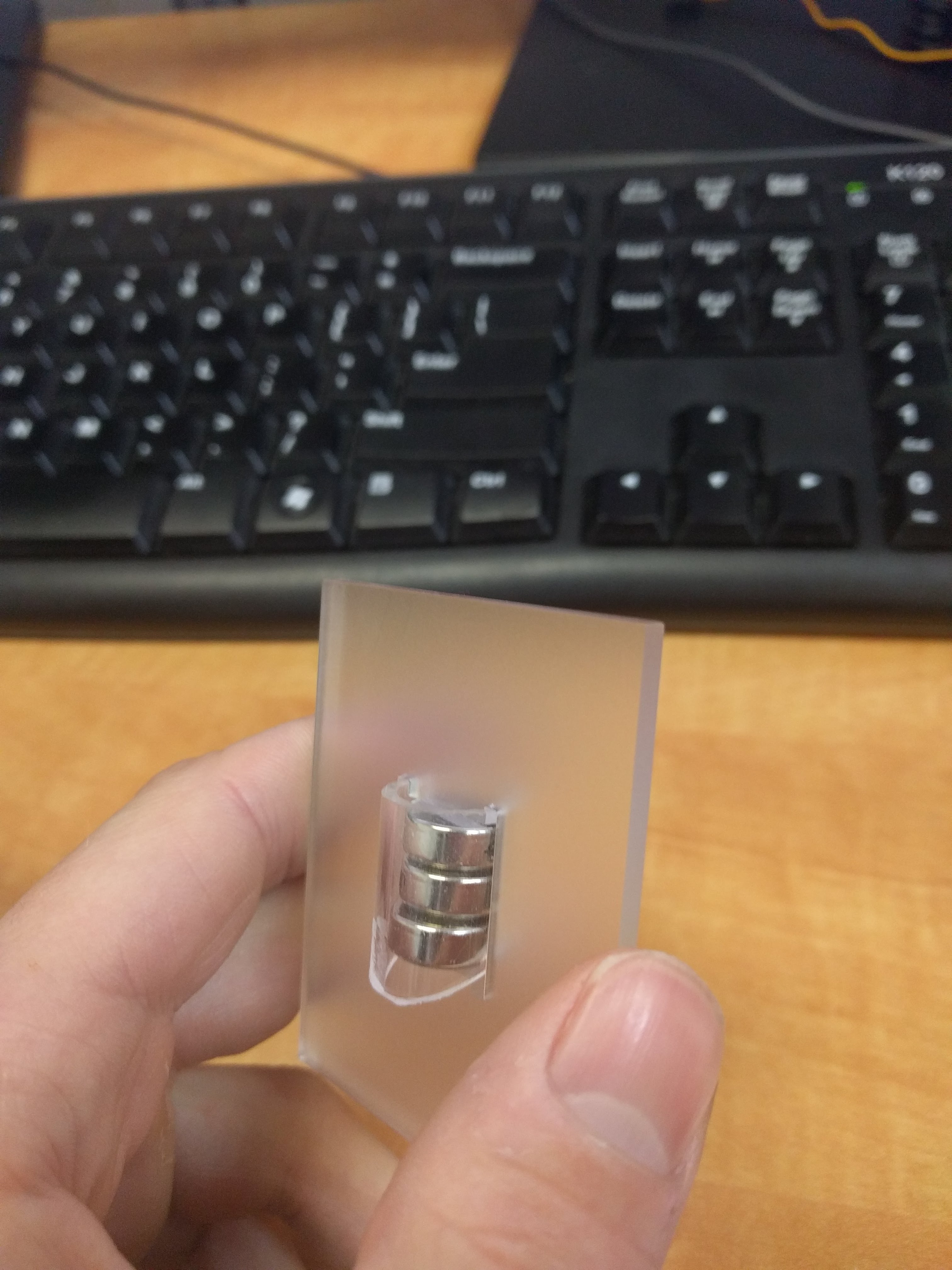
After some hemming and hawing about how to mount them exactly, I found an acrylic tube with a 12mm ID (just barely larger than the batteries), cut a slope into one side so that it can be inserted into the slot and then rotated to lock in. On the PCB, there is battery spring on one side, and some copper braid on the other to hold the batteries tight and make electrical contact. This solution works better than it has any right to, it is fantastic but blows my “manufacturable” requirement right out of the water.

For driving my LEDs – twenty per semicircle – I used a TLC5947. It’s a constant current, 24 channel PWM LED driver, controlled over SPI(a requirement for speed). There are two of them, and they seemed to work well, with one caveat that I’ll get into in a bit.

There is an interesting power section that I never ended up populating. The goal with it was to have a switch mode power supply attempting to boost the battery voltage to 4 or 4.5v from whatever voltage the batteries sag to. The idea being that with fresh batteries, it wouldn’t be doing much of anything, but as the battery runs down (internal resistance gets higher), the power stage attempts to pull more and more current to keep the output rail steady. The circuit ended up working fine with all of that jumpered over and direct from the battery, but it was an option in case that hadn’t turned out.

I also had a clever system on there to ensure proper polarity to my circuit regardless of how the batteries were hooked up, but again, didn’t matter enough for this version to use.

The TLC5947 has an SPI output pin to allow chaining multiple chips together, but naturally, it would halve the refresh rate I’d be able to get. I ran a trace between the two chips, just in case, but I was also able to avoid using that. The dual effective SPI ports I managed to get working(written about in a previous log) saved me from that.

Early tests were promising – I quickly got a recognisable image of the world showing.
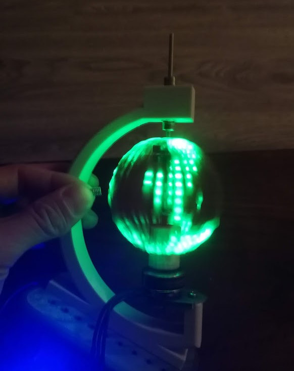
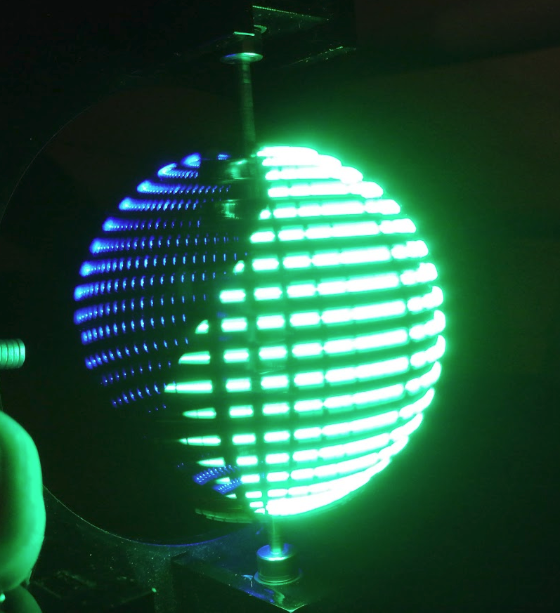
Introducing blue turned it into an unrecognizable mess, though. All further testing stuck to green, for now. The problem is that my hot glue light diffusion is too good, and allows light to be directed back through the sphere. Some sort of baffle on the inner side of the LEDs is needed.

An additional problem that I hinted at in the last logs is that my vertical resolution isn’t really high enough. The world map is recognisable, if you know what you’re looking for, but it isn’t fantastic.

And the final problem, the real deal killer: the TLC5947 blanks its output before displaying the next value. That is, a channel displaying 255 (full on) when a new value is sent to it, even if the new value is the same. It will go 255->0->255. That’s why you can see vertical gaps in all the images I’ve posted. This is mentioned nowhere in the documentation, and is just poor design. So future version will have to rethink this portion, too.


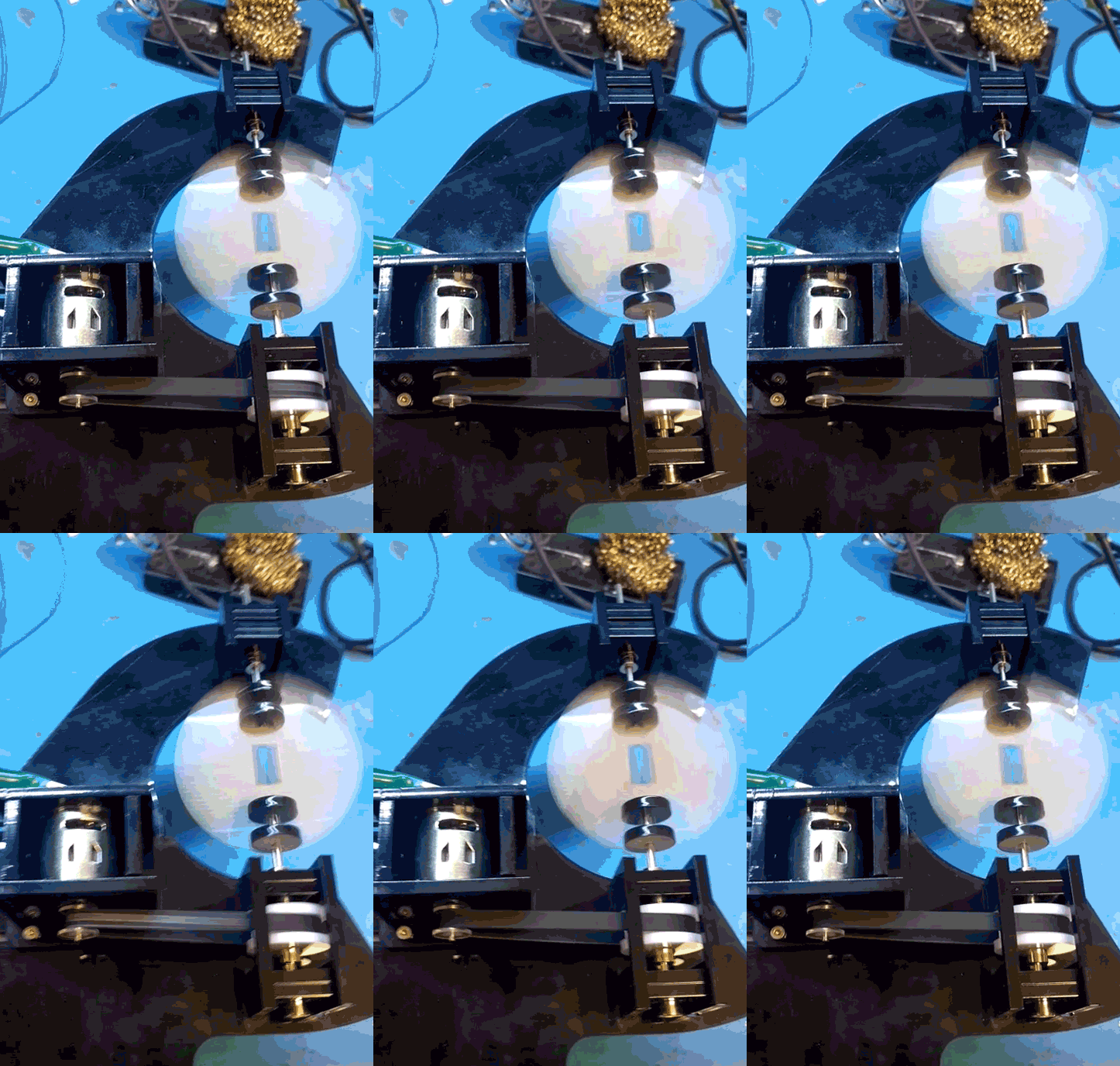
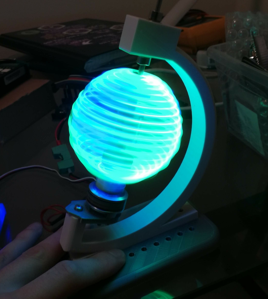
For the mechanicals, due to an unfortunate move, the old system got a little bit damaged and I 3D printed a replacement. This one also uses a direct drive brushless DC motor instead of the old brushed motor and DC motor. Again, just for fewer components and faster to put together.
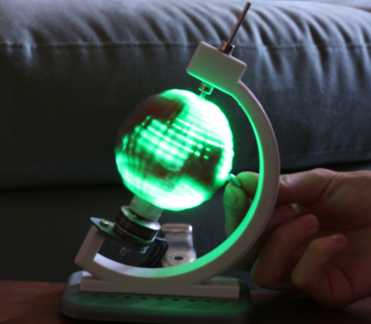
 

It worked well, other than some harmonics causing a lot of vibrations on some narrow bands of frequency. Future versions would also have a proper magnet holder, my hand is not a permanent solution.

POV Globe – The Mechanicals

The mechanical design for this project follows the “as quickly and easily as possible” maxim even more so than any other section. I used flat pack laser cut design strategies that results in pieces that snap together. I like that because it could in the future be turned into a kit reasonably easily, and in the meantime, it’s just a quick way to design and iterate.

For this first version, aesthetics plays no part, I just wanted to get the PCB mounted and spinning, along with an appropriate motor.

I used off the shelf mechanical components wherever possible, too. Standard bearings, shafts, collars, and couplers. Oh my.

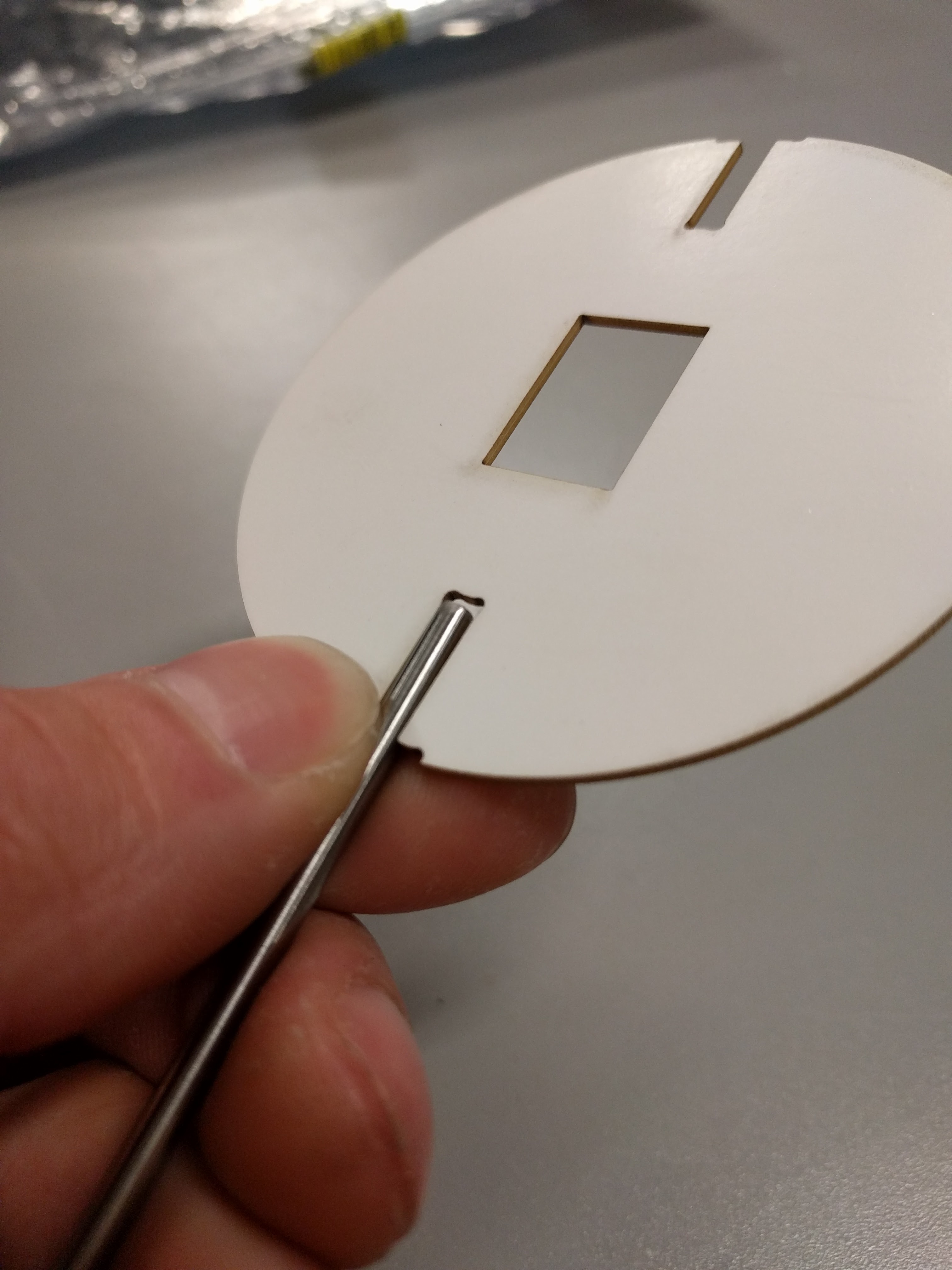
Coupling the PCB to the drive shaft was a challenge that went through a few ideas to keep it manageable. Something off the shelf, or quick and cheap to manufacture. 3D printing is right out. This picture illustrates the problem, along with a laser cut mock up of the PCB:

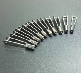
One of the solutions I explored was to use clevis pins, intended for RC helicopters.

I found some aluminum ones and some nylon ones, but the former ended up being unsuitable for size. The nylon still wasn’t perfect, but here’s a tip for when your shaft is inappropriately large:

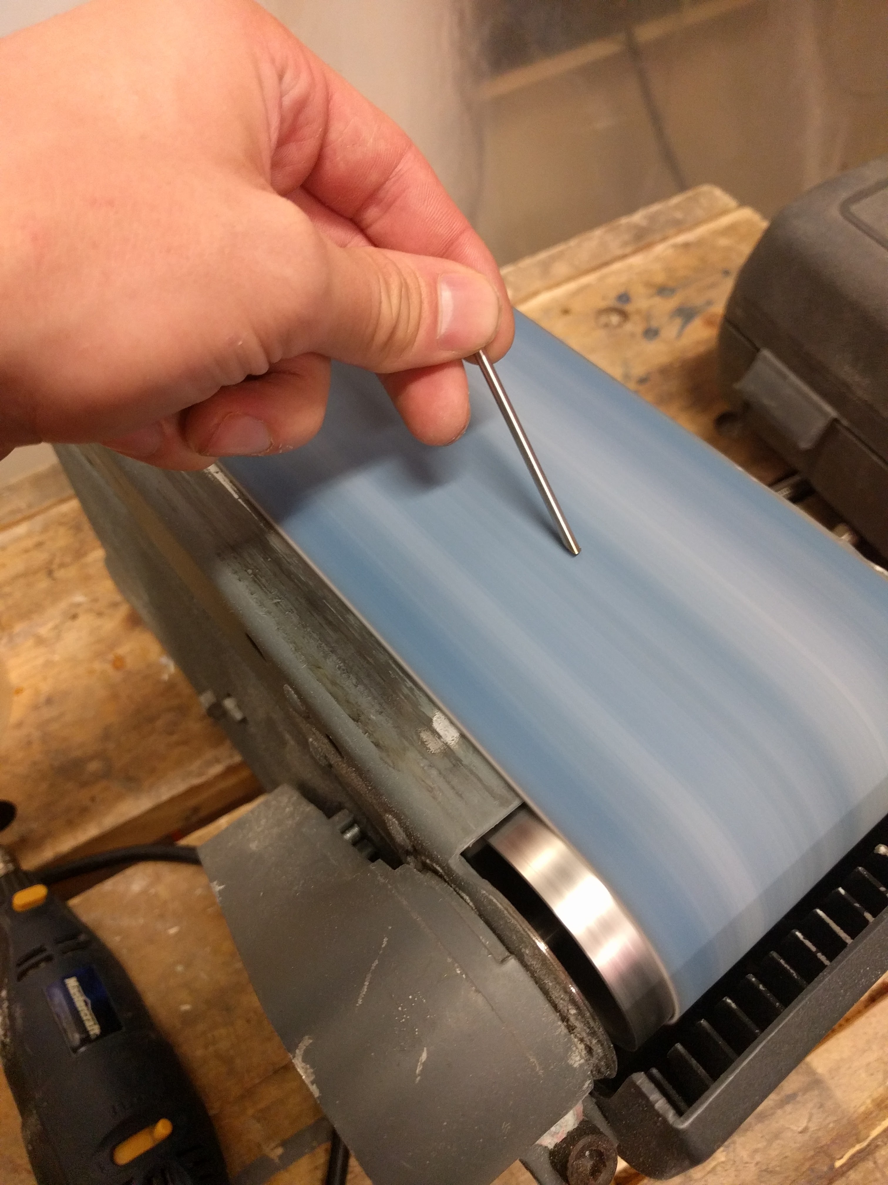
You can grind down steel rods to make a serviceable cutting edge, turning it into a poor-but-functional drill bit. Then they’ll drill right into the nylon.

One more issue was battery holding. Ideally, I wanted a cylindrical battery (or batteries) held longitudinally in the centre of the sphere. That seemed best for keeping the spinning disk balanced. For electrical reasons, I chose three LR44 coin cells stacked up to make 4.5v nominally.

After much fruitless battery holder searching, I grabbed a 12mm ID acrylic tube, and cut away part of it such that it could be fit into the PCB and then twisted to lock it in place. Like so:

That actually locked together pretty solidly, and I added a battery spring to the PCB to hold the batteries together.

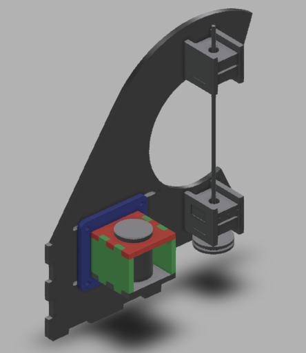
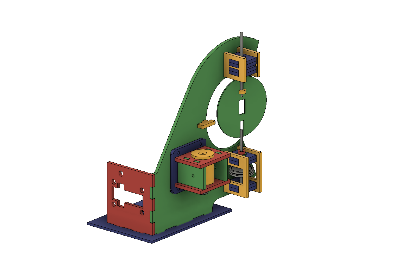
For the overall frame, I tossed something together in Fusion 360:

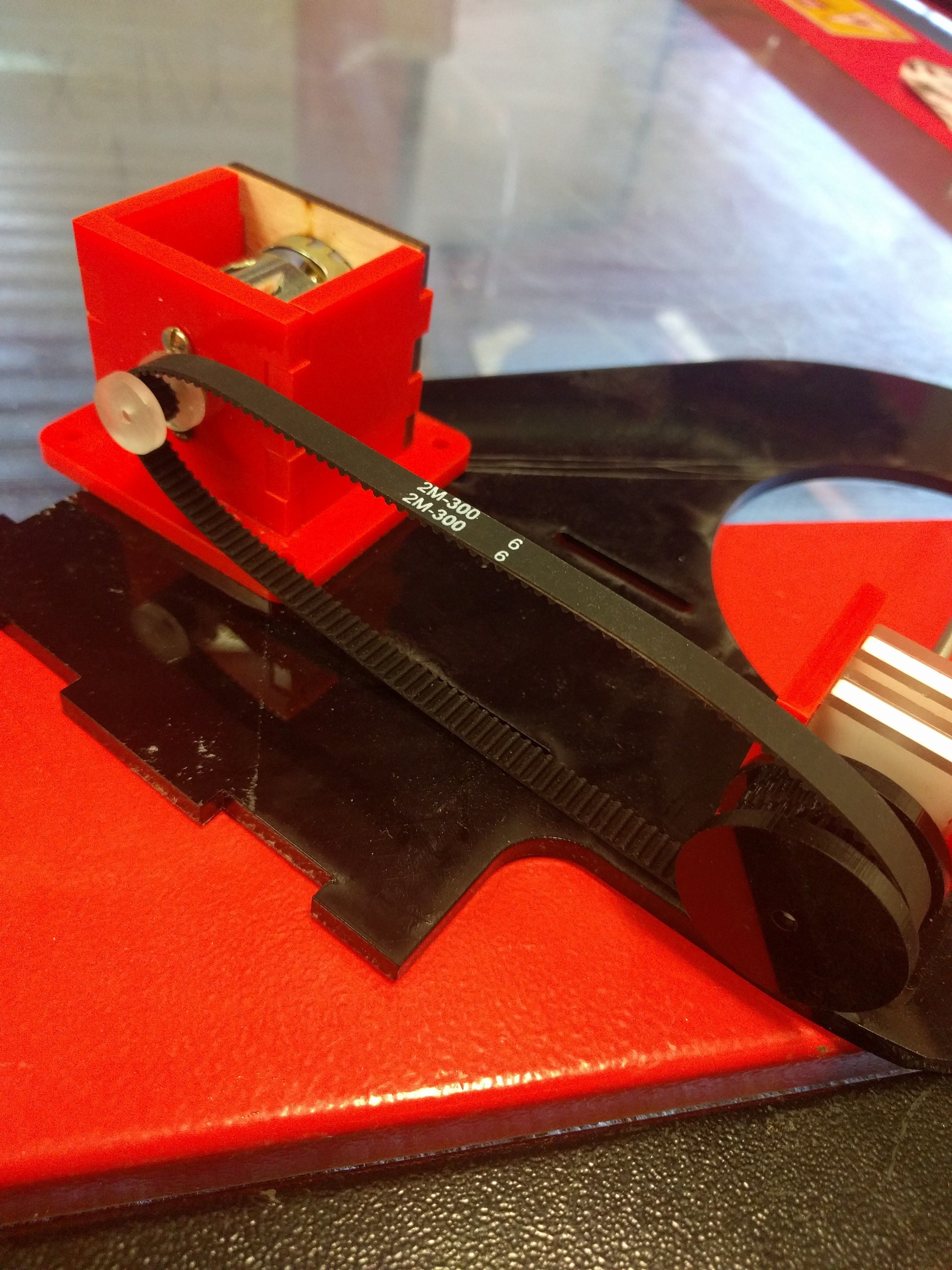
With the very first cutting, made from totally scrap laser material – mostly acrylic, but some plywood in there for good measure – I found a minor setback: I had the wrong belt size.

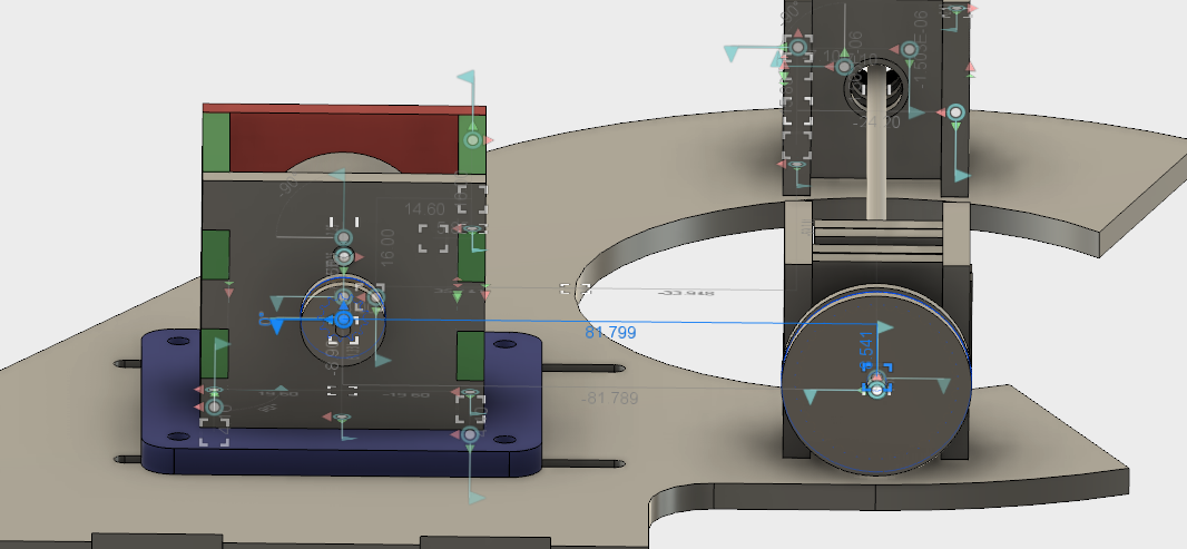
I’m not sure if I calculated wrong the first time, or did some redesigns after purchasing my belt or what, but a second calculation did confirm that my on-paper expectations should have matched my physical fit. I had a 300mm belt, but 82mm between centres at the middle of the adjustment distance, so there was no way that was going to fit.

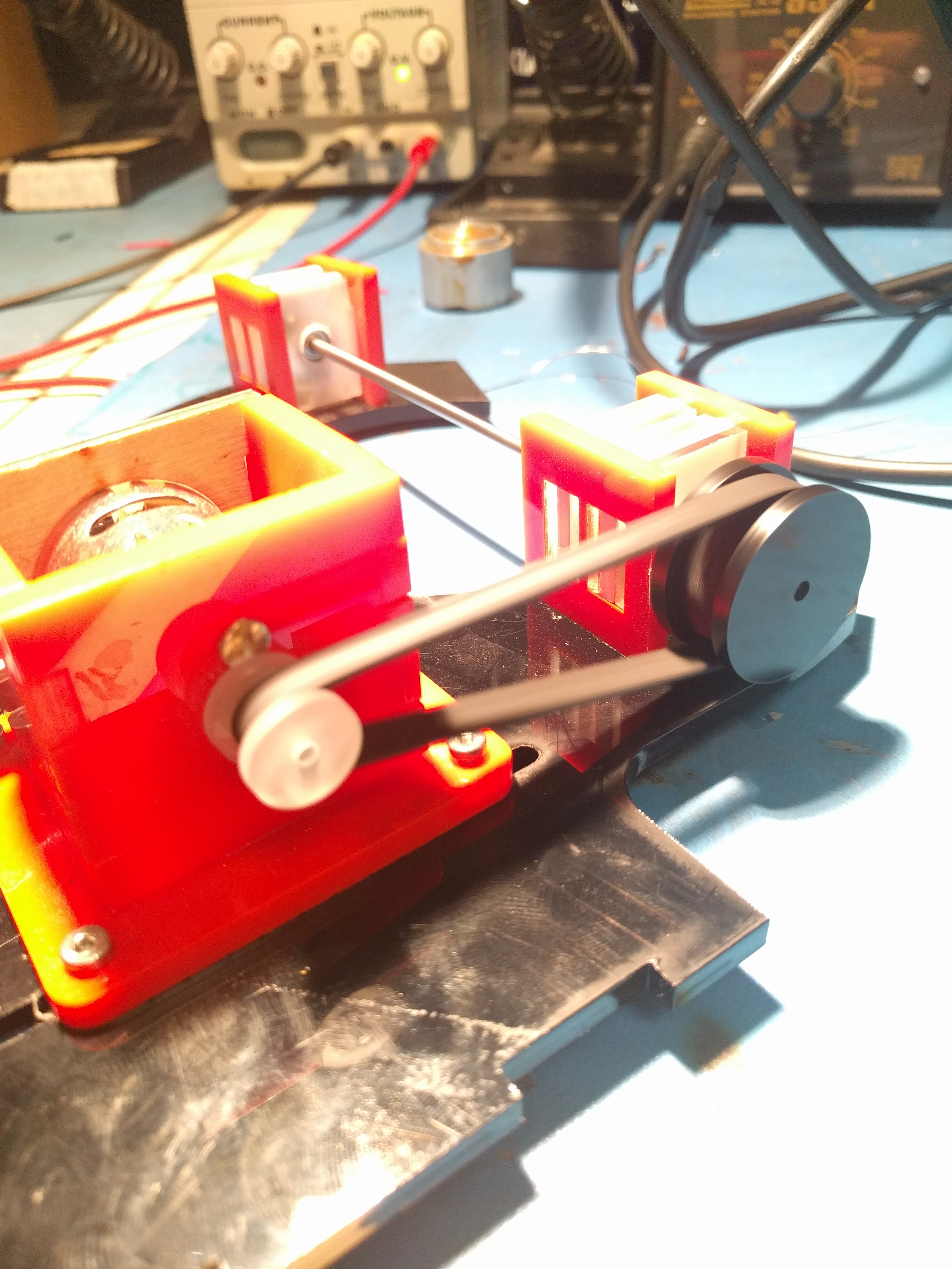
A 200mm belt proved much more suitable and revealed the next issue, which I vaguely suspected would crop up.

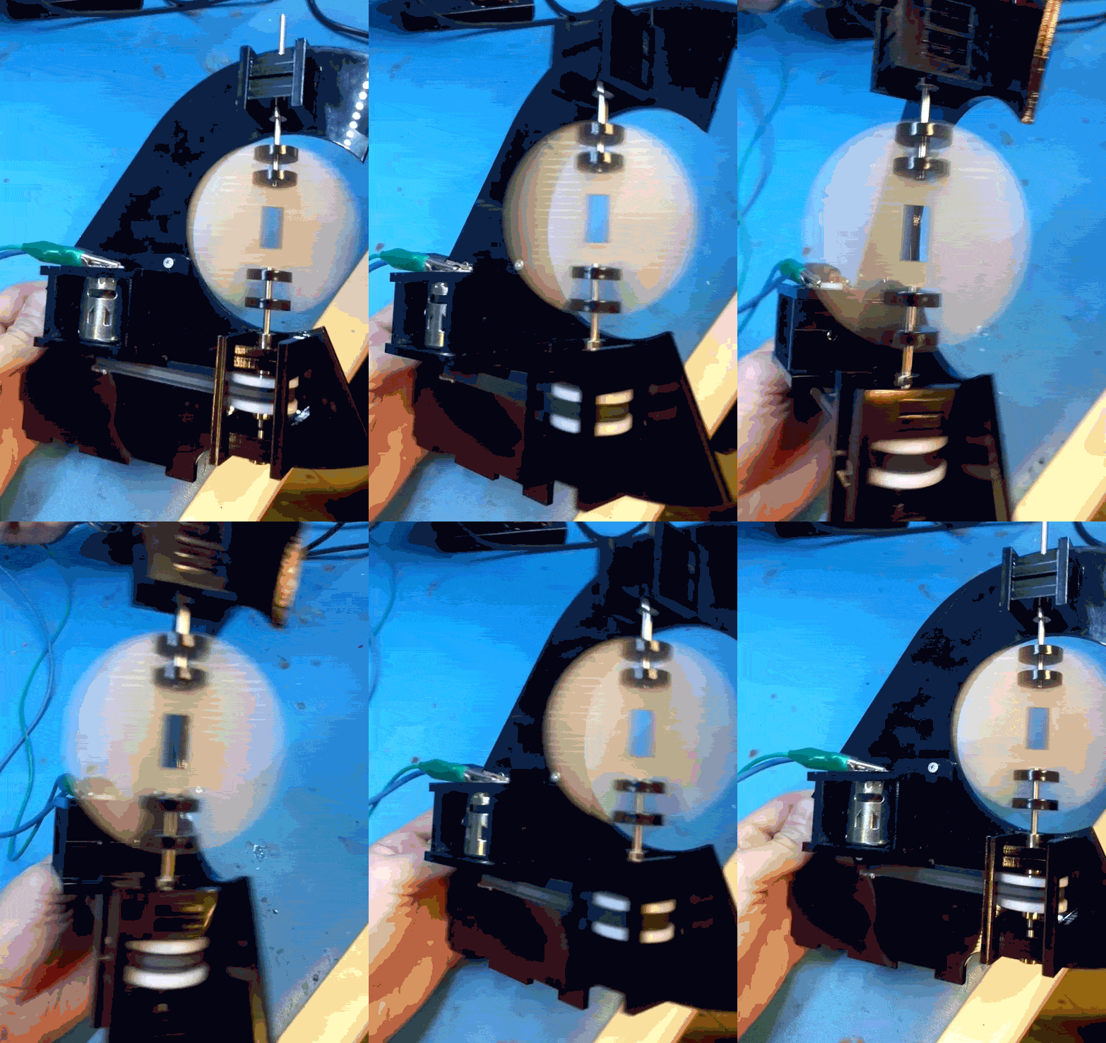
First of all, the system worked. Laser cut pulleys work great, I’ve used them before on other projects, and my tension and belt driven design seemed good.

When that main shaft got split and attached to my PCB mock up, however, the shaft was no longer properly supported.

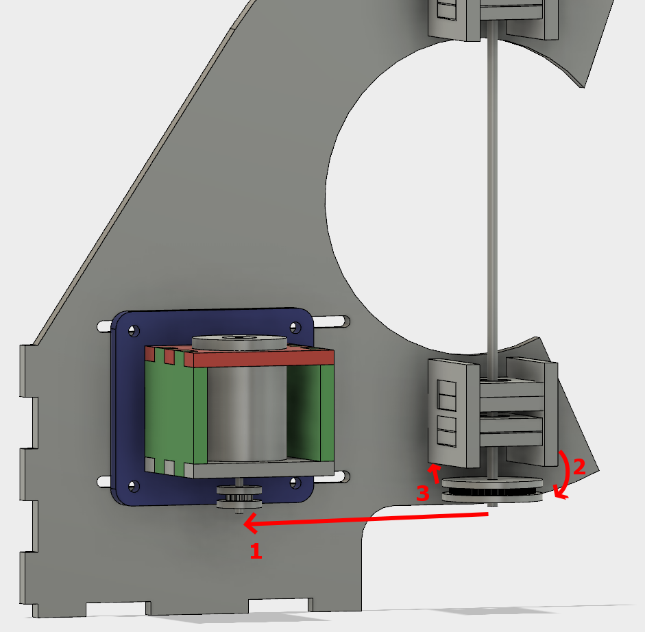
The belt put leftwards force on the shaft (1), causing it to cantilever in that direction (2), and then cause the pulley to rub against the bearing block (3).

I was hoping that the two bearings above the belt would fully constrain the system, but alas, there is too much flex in the shaft or slop in the cheap bearings, with not enough distance in between them.

So, version two. This time with a supported shaft on either side of the driven pulley. I was trying to avoid that because the design and assembly both get a little more complicated.

One more change was getting rid of the clevis pins. They rattled and I didn’t like them. Instead I swapped the smooth shafts out for D-profiled versions, and laser cut a notched circle to couple with the PCB.

After cutting and reassembly, it works great!

No more mechanical changes need to be made for this prototype to demonstrate that it works. Next section!

POV Globe – The Software

Persistence of Vision globes are a relatively simple project that everyone has to build, it seems. The fusion between mechanical, electrical, and firmware domains lead to some interesting challenges that are deceptively difficult to overcome.

It’s a great project with a low barrier-to-entry, but it’s also easy to put your own spin on it. Heh. Spin.

Teaser:

This post will only focus on the software (embedded and desktop), with other sections to follow.

Initially, the rough code flow for the PIC microcontroller for this was going to be:

  1. Rotate Hall Effect sensor past a magnet, sending a signal to…
  2. An input on the PIC, generating an interrupt
  3. Copy a timer’s internal value to a variable
  4. Clear the timer
  5. Divide the variable’s value by horizontal pixels to get transition times
  6. Set an interrupt at the next transition
  7. At interrupt, change the interrupt to trigger at the next transition
  8. Set data pointer to start of the vertical pixel data array
  9. Send out data at pointer via SPI to LED drivers
  10. Goto (7) until (1)

But that was before I discovered a new, amazing peripheral that some PICs have! Even the PIC16F1619 that I happened to be prototyping with.

It’s called the Angular Timer, and it’s pretty much designed for these applications.

The process is now:

  1. Set up AT with input, period, and and interval interrupt settings
  2. At period interrupt, set horizontal data pointer to zero
  3. At interval interrupt, send vertical line data at pointer via SPI to LED drivers
  4. Increment horizontal data pointer
  5. Wait

Substantially simpler, and much more responsive than polling and manually changing timers would be. The only thing that’s missing is a DMA peripheral, which only a few of the 8-bit PICs use.

This link to all of the files, code, firmware, mechanicals, and PCB are all on the Github repo.

In lieu of an elegant image update method for Revision 1, everything is hard coded into the firmware. The world map for the globe is stored as a set of arrays, and generated by a Python tool I wrote. In the tools folder of the above Github link, there is complete documentation. The gist of it is that you can pass it a PNG image, and it can process that image in a few different ways and spit out another PNG, CSV, or generated C files. Then simply include that C file in your firmware when programming the project.