Persistence of Vision globes are a relatively simple project that everyone has to build, it seems. The fusion between mechanical, electrical, and firmware domains lead to some interesting challenges that are deceptively difficult to overcome.
It’s a great project with a low barrier-to-entry, but it’s also easy to put your own spin on it. Heh. Spin.
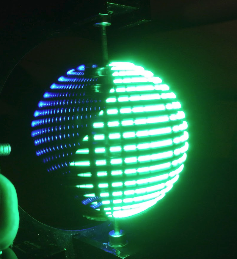
Teaser:
This post will only focus on the software (embedded and desktop), with other sections to follow.
Initially, the rough code flow for the PIC microcontroller for this was going to be:
- Rotate Hall Effect sensor past a magnet, sending a signal to…
- An input on the PIC, generating an interrupt
- Copy a timer’s internal value to a variable
- Clear the timer
- Divide the variable’s value by horizontal pixels to get transition times
- Set an interrupt at the next transition
- At interrupt, change the interrupt to trigger at the next transition
- Set data pointer to start of the vertical pixel data array
- Send out data at pointer via SPI to LED drivers
- Goto (7) until (1)
But that was before I discovered a new, amazing peripheral that some PICs have! Even the PIC16F1619 that I happened to be prototyping with.
It’s called the Angular Timer, and it’s pretty much designed for these applications.
The process is now:
- Set up AT with input, period, and and interval interrupt settings
- At period interrupt, set horizontal data pointer to zero
- At interval interrupt, send vertical line data at pointer via SPI to LED drivers
- Increment horizontal data pointer
- Wait
Substantially simpler, and much more responsive than polling and manually changing timers would be. The only thing that’s missing is a DMA peripheral, which only a few of the 8-bit PICs use.
This link to all of the files, code, firmware, mechanicals, and PCB are all on the Github repo.
In lieu of an elegant image update method for Revision 1, everything is hard coded into the firmware. The world map for the globe is stored as a set of arrays, and generated by a Python tool I wrote. In the tools folder of the above Github link, there is complete documentation. The gist of it is that you can pass it a PNG image, and it can process that image in a few different ways and spit out another PNG, CSV, or generated C files. Then simply include that C file in your firmware when programming the project.