Key Storage

I’m on a home improvement kick. When I walking my home, there’s a long, featureless hallway with kitchen at the end of it. I was using a tray on my kitchen counter to toss keys onto when I walked in the door. This takes up valuable kitchen counterspace, and being at the end of the hallway, was not ideal.


I designed up a wall-mounted tray that looked kinda nice. Then I CNCed it out of a scrap chunk of pine. I did a bad job estimating the size, so it turned out way too small and not really usable.


Instead of just recreating it, but larger, I an additional feature to hold cards would be useful. Additionally, the CNCed wood required some hand sanding that I didn’t really want to deal with again, not to mention the CNC setup time.

None of that was particularly time consuming or difficult, but honestly, it was faster and less tedious to 3D print it and cast it in cement than to break out the CNC again.

With the larger size, I wasn’t so sure about just slotting it into a piece of plywood without supports, so I added a steel cable. It’s a nice design accent regardless.

Note the knotted up steel cable in the mould. I also used XTC-3D, a resin coating designed to smooth out 3D prints. It was expired and a little chunky, but still seemed to work well. I’d use it again. The resulting cement form was smooth and required no post-

processing.

I also designed a tensioning mechanism for the cable. There’s a captive screw that drags a nut up and down. The nut assembly holds the cable end. The whole assembly slides into a 3/8″ drill hole. At the top of the assembly, there is a hole that is sized just right for a screwdriver to come in and engage the screw, dragging the nut assembly closer, tightening the cable tension.


For the backing, I made a drill jig to be able to drill straight down the 3/4″ plywood without breaking through either side. The steel cable goes in, and then I attached it to the tensioning mechanism with a combination of melting the plastic to it, and some CA glue for good measure. The whole assembly then also got glued into the drill hole.

After all of that was set up, I used plumber’s putty epoxy to fill in all of the gaps between the tray and the plywood, and bolted it to the wall!


This project went just about as smoothly as possible, probably about 6 hours all told.

The Worst RC Car in the World

Quite some time ago now, I wanted to make some of remote control car. And, also, eventually turn it into an autonomous sumobot or similar.

This project was done a few years ago, but I’m writing it up now.

In the interest of getting something into my hands that I can iterate on, I did it as quickly as possible.

Yes, that is a structural q-tip. The cardboard was collapsing.

This crappiness is actually a feature – because I introduced this as a workshop to a bunch of people. Mostly beginners, with minimal exposure to electronics or microcontrollers.

Operation is simple. You program it in with your WiFi credentials, then when you turn it on, it creates a webpage that is just a joystick. That controls the car. It’s surprisingly satisfying.

The repo is here. It includes materials and code.

Everything in this sort of direction in the future will be a little bit more complicated or interesting, I just wanted to break the seal.

The fun in this project is quickly and cheaply building something simple, that can be controlled easily. No part of this is too hard to understand, and therefore, improve.

So with that in mind, I ran a few workshops to get other people started.

As a fun detour, I took the opportunity to play around with a vacuformer.

I modified a VW beetle model to remove the front fenders to better fit the single castor front wheel, then 3D printed the buck.

This is in parallel with designing an internal frame to hold all of the components together. For personal stuff, I usually use OnShape for my CAD, lately. The free version forces designs to be open source / publicly searchable, which is pretty great when banging together AliExpress modules. And also for the base VW model to modify into a tricycle.

Rock Planters Rock

I’ve been wanting to play around with concrete for a while, as a project material. I’m not sure what the end goal will be, but once I’m familiar with the material, I’ll be able to shoehorn it into other projects in unexpected ways.

Concrete (actually cement, as I don’t intend to add aggregate) is different from other casting materials like silicone or resin in the cost/quantity proposition. Silicones are quite expensive, often purchased in 1L volumes or so, while cement has the opposite problem. It’s cheap, but I’m stuck buying 40 pound bags of the stuff.

Initially, I found some geometric molds off the internet and started with that, along with a convenience store drink cup.

It was easy and worked quite well.


I used RapidSet cement. The box is blue. There are many different kinds, and apparently this is one of the lightest in colour, while being a little smoother than most.

To make these into decent planters, there are also two additional steps: soak it to get all the lye out, and then seal it so it doesn’t shed cement dust all over.


The sealant foams up all strangely. It’s a granite countertop sealer.


This was all just practice, so that I would have a feel for how it works before I put a ton of time into something cooler.

I wanted to cast a mountain range (or two!). I really like mountains.

I started with Mount Currie – A distinctive skyline feature near a town called Pemberton. Also as a learning exercise with Blender; I’d never used it before.

Here’s the view from a place I stay at sometimes:


I grabbed the geodata with TouchTerrain. Here are my settings:


Then in Blender, I set up the camera in the same-ish position and focal length of my camera.


Yeah, I’m very satisfied with that.


Next step, make the renderer export a depth map instead.


Then map it around a cylinder as another displacement map. The nice thing about this is that the Blender portion of the work, which I’m not very comfortable with, is done. So I’ve got it set up just right, and I don’t have to touch it – The rest of the fiddling on this model is with 2D depth maps in Krita, an open source Photoshop facsimile.

I faked the sides of the mountain range a bit, because they don’t just drop off to nothing.


When I got it how I liked, I 3D printed it to get a feel for how it looks in the real world. A few back-and-forths with that, and I built a mould around the positive model in Blender.


Each piece took about 24 hours to print. This is surplus PLA that will never otherwise get used so the volume of plastic used is totally okay, and the size (and therefore weight) of the cement involved is a concern for a mould that would be more plastic efficient and less beefy.

And then I poured.

The thermal camera shows how hot it gets as the cement starts to kick. It got past 60 by the time I left it for the night.

I actually did it twice. The first one I didn’t mix up enough, so ended up scrambling to mix more, which didn’t fill in the mould completely. Honestly, I kinda like it.


For the second attempt, the mould had warped enough that the seam lines were very visible. After the second pour, the mould had warped enough that it wasn’t viable to pour a third time. This is a really interesting datapoint. It’s possible that PETG or some other higher temperature material would fare better. And this issue doesn’t crop up in the smaller castings I did. The cement only gets hot enough to deform the plastic when there’s a large volume curing at once.


But regardless. The result!

It’s decent. I’m about 80% happy with it. It’s recognisable as the target mountain range, but it’s not instantly identifiable. This is done as the actual aspect ratio of the mountains, with the focal length of the (cellphone) camera I took of the mountains, and it looks a little too shallow. Perhaps the aspect ratio would be a good knob to turn for future experiments, to get the mountains in the casting to look a little taller.

Force-Directed Circuit Board Footprint Autoplacement

From Wikipedia:

Force-directed graph drawing algorithms are a class of algorithms for drawing graphs in an aesthetically-pleasing way. Their purpose is to position the nodes of a graph in two-dimensional or three-dimensional space so that all the edges are of more or less equal length and there are as few crossing edges as possible, by assigning forces among the set of edges and the set of nodes, based on their relative positions, and then using these forces either to simulate the motion of the edges and nodes or to minimize their energy.

Force-directed graphs are a common way to display things like mind-maps. It’s a good way of spreading out the whole collection, while grouping related items together, and minimizing the path length between the closely related items. In my mind, this has a lot of similarities with how PCBs are laid out.

Well, there’s only one way to prove that theory.

KiCad Footprints animated in an exploding fashion

Using KiCad PCB parsing code I wrote for another project, I was quickly able to grab the nets and footprints out of a KiCad project. Displaying the nets and allowing specific ones to be turned off was a feature I identified as critical early on, because the ground or power nets would overwhelm any of the others, rendering the important nets useless.

Truthfully, a significant part of this was wrangling TKInter to build the Python GUI that I wanted. It was a success, but I’ve never used it before, and I am not a fantastic UI designer.

Under the hood, the system essentially treats each of the nets as a spring, and applies a simplified version of Hooke’s Law to each connection. Each of the centre point of the footprints acts as a charged particle, and a simplified version of Coulomb’s Law acts upon it to repulse all of the other footprints. These algorithms are a pretty typical way to do this, by essentially setting up a physics simulation. One tweak on this strategy that is unusual, is that the nets don’t act on the footprint origin. They act on the pad itself, which allows a torque to impart a rotation on the footprint.

I’ve gotten this project as far as “fun tech demo”, and it’ll likely fall dormant for a while in this state. At some point, I will build an appropriate PCB using this technology, because I love making unusual designs that are electrically fine.

The repo is here. Have at it.

Strange New Bedroom Furniture

I bought a used lathe.


It’s a Craftex B1979C, which seems to be nearly identical to a Craftex CX704. Similar to many such mini lathes, actually, with varying swing lengths.

The previous owner explained, a little bit sheepishly, that he tried to cut steel a little too hard, and burned out the AC motor. He replaced it with a hobby BLDC motor and ESC, designed for things like quadcopters.

I played around with that system a little bit, and I didn’t like it.

Annoyingly, he bought a $50 motor and a $50 motor controller, both sensorless versions. For these kinds of motors, you need sensors to start up at low speeds with torque on the motor. That would have cost $60 for the motor and $60 for the motor controller – Not much extra for him, but annoying for me to have to shell out the full amount for both, and then have the old ones as somewhat useless spares.

Anyway, instead of going the same route, I chose to get a more sophisticated controller so that I could precisely control parameters, like speed, or acceleration. The options are essentially vESC or ODrive, unless I want to custom build something myself (I do not).

The ODrive, at least on paper, looked a little cooler. Some good communication strategies, lots of control modes, and generic enough to work well for this somewhat strange application. Right after I’d picked mine up, they discontinued support of the V3.6 and went to a closed source model, which rubs me the wrong way. The new version is also more expensive and has a single channel instead of two channels. One of the big issues with the legacy release is that there is a bug in their UART driver – If you send enough malformed packets, like, say, because you have a data line right next to a spinning motor, then the controller eventually stops responding to all UART data. That can be an issue when the packet you want to send is “stop now, immediately”. That definitely hastened my building of a separate e-stop box.

Fortunately, after I wrote a CANBus driver and used that, it’s been reasonably solid. That was just more of a time investment than I wanted to make.

I built a front panel for it as well. It’s a couple simple PCBs holding the switches, OLED, buttons, and a dev board. The advantage of not including everything on a complicated PCB is that I can pop out the dev board to flash it on my bench, before returning it to the lathe. The dev board is an ESP32, which is driving a little OLED screen that shows the target and measured speed, current, forward and backwards directions of the motor controller. The list of features I could add is nigh-infinite, but this is good enough for now. Oh, and I can do software updates over the internet! There is no way this can end badly.


It’s weird how sometimes three sentences can encompass four months’ worth of occasional project time.


The change gears the lathe came with are steel, which is unusual for a model like this. It came with a set of gears, from A-D: 20/80/20/80. However, this combination isn’t listed on the table anywhere.

The formula is ((A/B)×(C/D))×lead_screw_pitch/initial_ratio
where you have a 3mm lead screw, and it has a 2:1 ratio. So for example, 0.4mm pitch is ((20/50)×(40/60))×3/2 = 0.4.

That means the gears I have are about 0.09mm pitch, which is good as a powered feed, but not intended for any kind of threading.

Most of the other examples of this family of lathes use plastic change gears. Obviously using cast or machined nylon, but with a little bit of babying, I bet 3D printed gears would be Good Enough.

As near as I can figure, the change gears dimensions are module 1, with a 20 degree pressure angle. And a thickness of 8mm.


To practice threading, I copied a bolt that I had on hand, which was 1/2″-13 TPI, using the table to get 40/65/60/30.


Looks neat! But my tool geometry is bad and the angles are all wrong, so I reset, bought some more tooling, and moved on to something actually useful.


3D printed change gears work great! I’ve printed off a whole set, and I’m stoked. Arbitrary threads are unlocked.


I wanted to turn a gear shift knob, which has a thread of M12*1.25mm.

Using the formula above, the gears I need are 50/40/40/60.

The outer diameter of the stock is about 11.85mm.


This process ended up being incredibly drama free. Twenty minutes after starting, I had a very-slightly too-loose thread, but it snugged right up when I tightened on the knob.


Success! Now to do some cool things.

Brass Lamp

I haven’t properly built anything with my hands in a while, so it’s time.


I mocked up a few lamp ideas, and this one seemed fun. Really, really rough mock-ups.


That was neat looking, so I fleshed out the hinge section, which I expected would be the hardest part to figure out and build.


First, I 3D printed the hinge, just to get a feel for if my sizes felt right – I am bad at judging size in CAD, things often turn out way larger or way smaller than I expect, and therefore really difficult to build.


These looked fine, though.


I picked up a ton of brass from a hobby shop. Can you guess what the main focus of the hobby shop is?


For the hinge pieces, I didn’t have the right shapes or size of brass stock available, so I needed to cut a bunch of smaller pieces and then braze them together with silver solder. And then took them to the belt grinder.


Pretty close!


And then tried to add one more piece, dropped it while the solder was molten, and had them splatter apart on the ground.


Okay one more time.


It’s always better the second time, anyway. I used an M1.5 brass screw as the hinge pin.


For the stand, I 3D printed some saw guides so that I could get the tube angles perfect. The stand wouldn’t end up with the right geometry unless the cut angles were just right.


Then, after brazing:


It matches up with my CAD perfectly, I’m stoked.


Some blu-tak was used to hold the hinge pieces and light backing together to get a sense of how it was all going to go together.


The light panel itself was a circle of aluminum that I spraypainted black. Then I riveted the hinge on and laid out my LED tape.


Wiring.

This could have been done much neater. Next time.

Encircling the LED panel, I bent some flat bar aluminum, riveted it, glued it, and painted it. Then glued on a plastic diffusion circle. This was all done quickly, so I didn’t take many pictures.


For the base, some nice dark wood would be ideal, but that would have required a fair amount of material acquisition and hunting down tools I wasn’t up for, for this project. So I took my base, and split it up into easily printable chunks.

I was going to attach them together, sand, patch, sand, and paint them to turn them back into one object, but I kinda liked the jigsaw effect, so I left it. PETG sands really well, and I treated it with a light oil coating to keep it from taking on fingerprints.

The pieces are just bolted together, and mostly hollow to allow mounting of the electronics.

For the controller, I have a surplus prototype lighting controller of dubious origin, and wrote some firmware to handle fading and mixing the two LED channels. The 24V power supply comes from AliExpress.

Similarly, for the knobs, I went for an easy and quick solution using 3D printing for the ends to retain a little bit of the brass tube onto the potentiometers. The left knob controls the light intensity, and the right knob controls the light’s colour temperature. This lamp can fade in between a really cool white and a really warm light.

Running the wires through the brass tube was a fun adventure. What I ended up doing was fill the tube up with oil, run a single wire up through the bottom, then solder it onto the other three wires. After that, I could use the first wire to pull the whole mess back through the tube. Then I flushed the tube with alcohol to clean it all out.

And, final wiring, and it works! It looks great. I can see all the small defects, but that’s okay. I’ll do better on the next one.

Dumping Firmware With a 555

Voltage glitching, also called fault injection, is the process of dumping the energy on a microcontroller’s power rail very briefly – Just enough to cause a glitch, where it skips an instruction, rather than causing a brown-out-induced reset.

I first learned about the technique in connection with the Chip Whisperer, which is an FPGA-based board with all the bells and whistles. It’s quite expensive, and like any other situation where you add an FPGA, very complicated. Naturally, that has elevated it to a level above what mere mortals can perform in the limited free time we have.

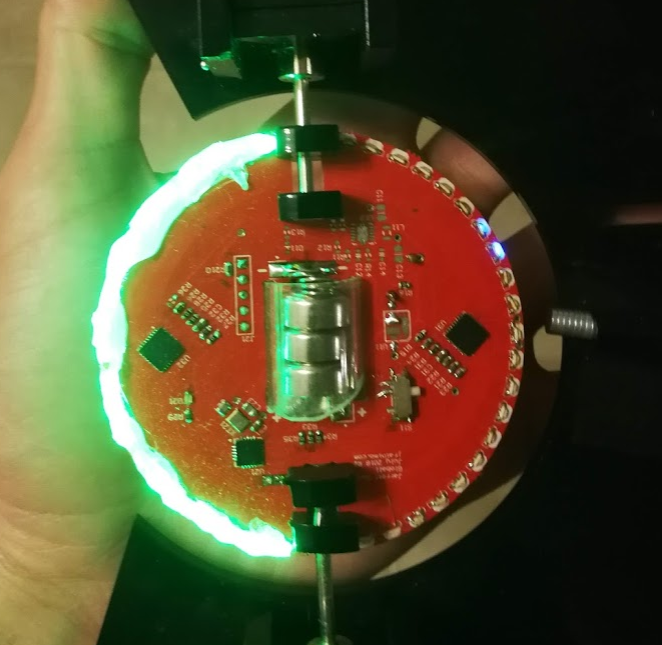
After knowing about this, and having it in the back of my mind for several years, I finally have a good use-case that can justify spending some time on this. I have a pile of generic STM8-based devices, and while I have written some of my own alternative firmware, I’d love to be able to dump the original flash to revert them back to factory code.

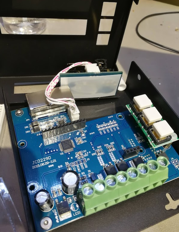
The function of the device doesn’t matter, that’s not the point of this exercise.

Some quick searching for options leads to this recent write-up, which is sparse on details, but serves as excellent inspiration that this task is very doable.

A few architecture notes:

The STM8 has a Read Out Protection bit in the configuration area of its flash memory. When the programmer attempts to read out the flash memory, the bootloader first checks this bit, and if it’s cleared, it starts reading out the flash to the programmer. If it’s set, it just reads out zeroes. Write capability is never blocked – That is, you can still write a zero to that ROP, and then the microcontroller will be “unlocked”, but it does clear the program memory, too.

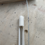
One of the pins on STM8s is called VCAP, and it’s attached to the internal voltage regulator. The CPU runs on this voltage rail, not the actual voltage that is provided to the IC’s power pins. The pin is intended to be connected to a decoupling capacitor, and that provides an perfect spot to inject my glitches. Most microcontrollers also have something called Brown-Out Resets: When the input voltage rails sags too low, the peripheral triggers, and resets the microcontroller. Obviously, this is something we want to avoid, and using the VCAP pin should help with that.

In terms of glitching, there are two important considerations:

The glitch must start at the same time or during the cycle in which the CPU is trying to read the ROP bit, and the glitch must not last long enough to trigger the BOR or to make any other important instructions fail. It’s not easy to know these exact timings, so any reasonable values must be tried, essentially brute forcing the process.

Now, the logical way to do this would be to use an external microcontroller to wait for the programmer to reset the system, wait a set period of time, and then trigger the output transistor to glitch the voltage rail. That’s boring! You know what else can do that? That’s right, a pair of 555s.

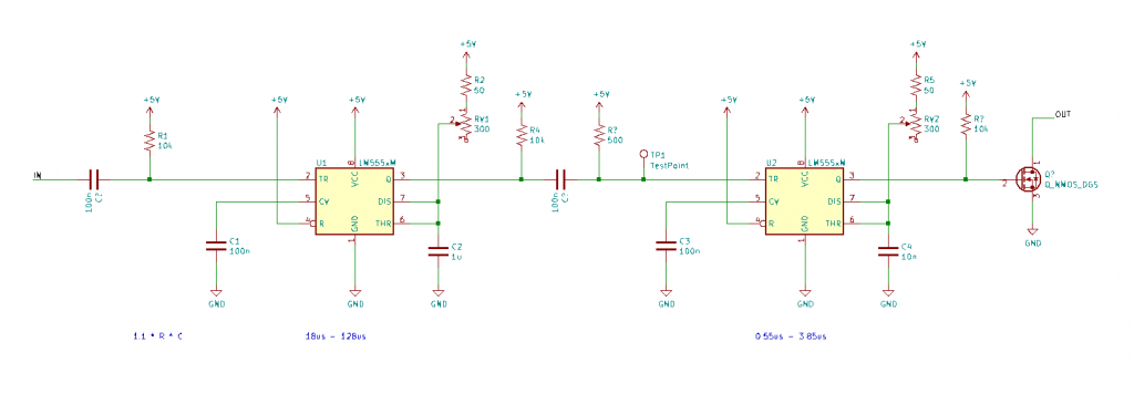
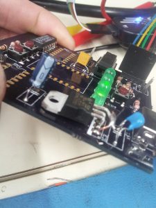
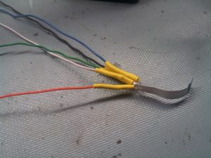
Here are two 555s set up as monostable pulse generators. The input is the RST line on the STM8 programmer. The first 555 then sets the delay. The second 555 sets the length of the output pulse. Both of these timings are controller by a different potentiometer. These then go to a MOSFET that dumps the energy stored in the internal voltage regulator cap.

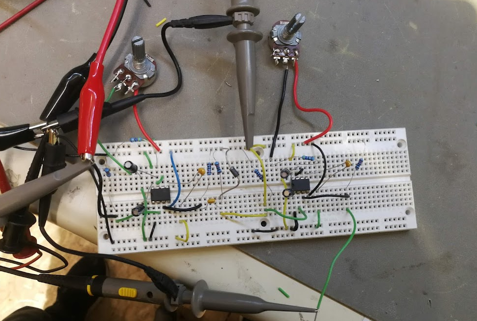
After building it with larger-than-designed time values and testing it to prove that the waveform looks as expected, we solve the next hurdle:

To figure out decent ranges for the potentiometers, my STM8 board runs at 8MHz, which means that each clock cycle takes 125ns. The STM8 requires at least 2 clock cycles for each instructions (one for retrieval and one for execution), and more for instructions with multiple bytes or arguments. So, ballparking, we need a pulse that’s anywhere from 0.2us to 1.2us or so.

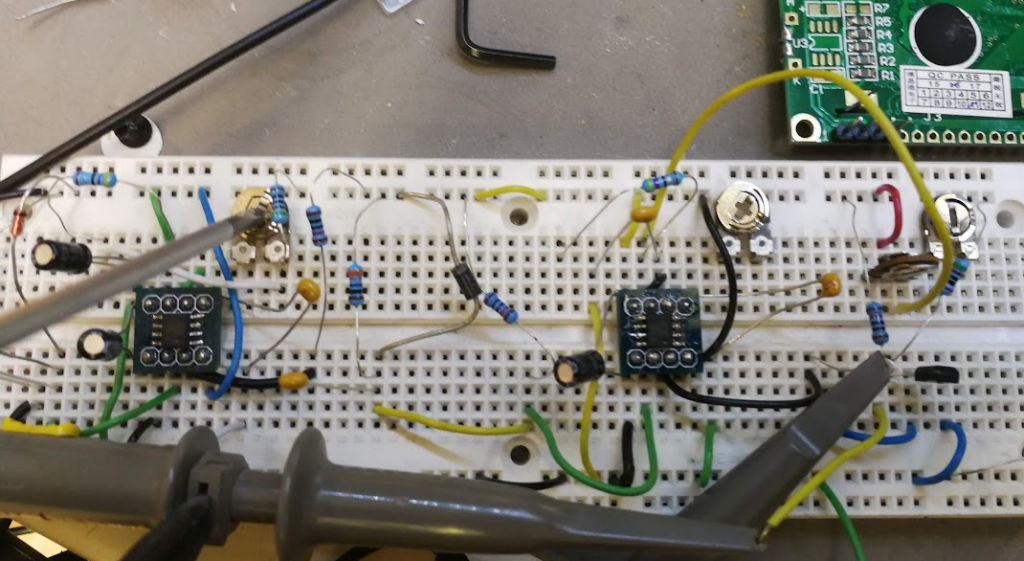
One problem with a typical 555 is that it can only generate pulses as small as 10us. Fortunately, I have a pair of high speed versions up my sleeve, the LMC555. It has a 10ns minimum pulse instead, which is very zippy. They’re SMD only, so they get popped onto a breakout board to fit the breadboard, and replaced. Some other components got tweaked too, as I played around more.


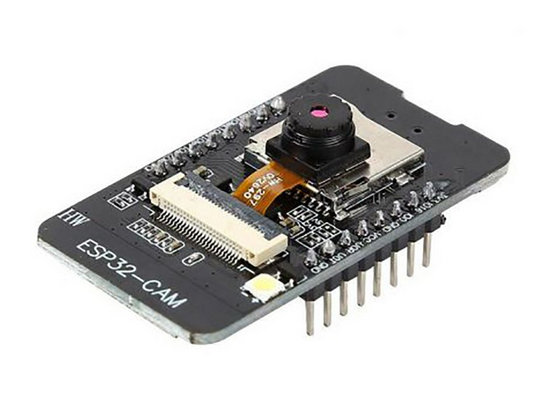
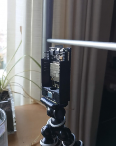
Now on to the programmer. I’m using a standard STLink V2, which speaks the SWIM protocol that allows programming and reading of the STM8’s flash.

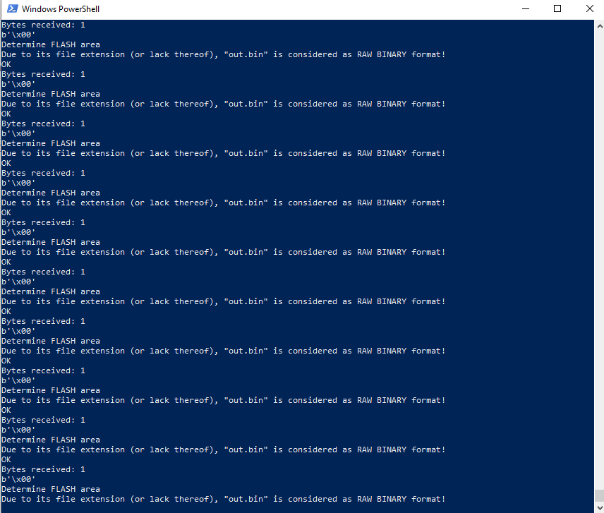
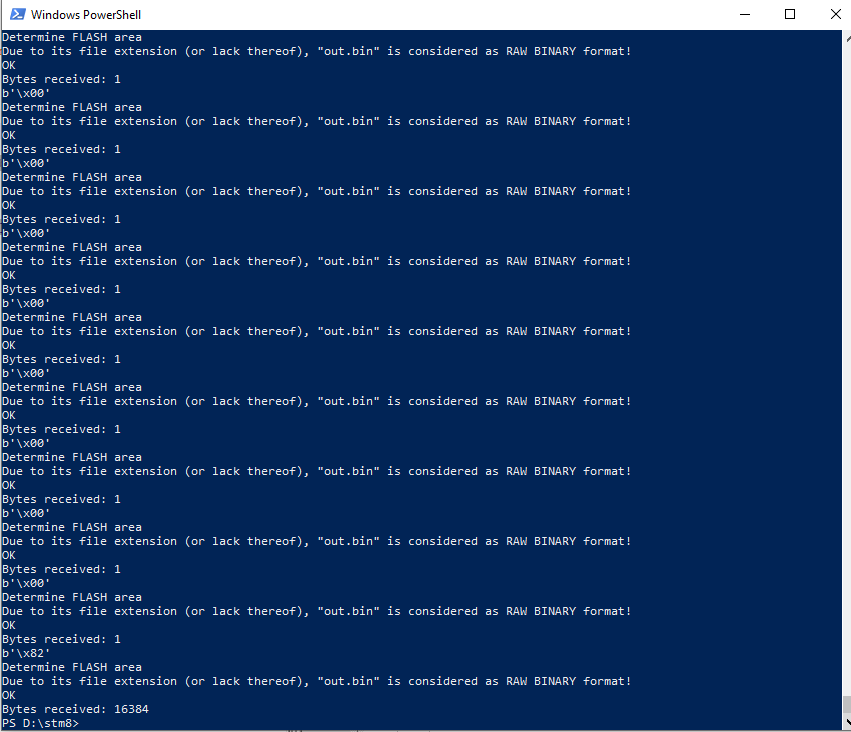
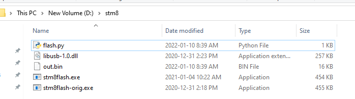
With a little bit of bit of Python and stm8flash, we get this:


import subprocess
# .\stm8flash.exe -c stlinkv2 -p stm8s105?4 -r out.bin -b 1
out = b'\x00'
while out == b'\x00':
subprocess.run(['stm8flash.exe', '-c', 'stlinkv2', '-p', 'stm8s105?4', '-r', 'out.bin', '-b', '1'])
f=open("out.bin","rb")
out = f.read(1)
print(out)
subprocess.run(['stm8flash.exe', '-c', 'stlinkv2', '-p', 'stm8s105?4', '-r', 'out.bin'])


In PC applications, writing text to console is a surprisingly slow process, so a low-effort tweak I made to make the loop run faster is to remove the flash utility’s console logging, just by removing some lines here.

So, all set up, potentiometer on the left controls the delay, pot on the right controls pulse length.
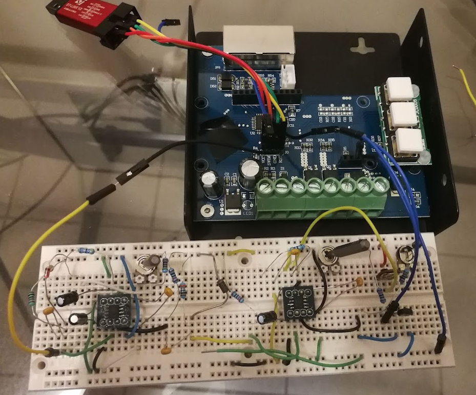
And, bam.

Firmware dumping with a 555.


Well, not that fast. It took about 45 minutes of fiddling with the knobs until all its secrets were unlocked. I’d sweep the right knob the whole way, then tweak the left knob very slightly, then sweep the right knob again. It only really worked because the knobs only had to be within the right range for a very brief period of time. It only had to work once.

Would this have been easier with a microcontroller? Oh yes, of course. But that’s not nearly as interesting.

Chromaticity

Here is a brief overview of how light and colour work, in the context of LED lighting.

We’ll mostly be discussing the CIE 1931 colour space, with reference to the chromaticity diagram, shown below.

This is the 1931 version. Newer versions that look slightly different have come out, but the general intent is the same, and they are all used for different calculations. The 1931 version is “good enough” and is universally the one that is referred to when a colour is described in xy coordinates.

The points along the edge are pure visible wavelengths (displayed in nanometres). Anything inside the diagram is some mixture of the wavelengths.

Computer monitors don’t have the same kind of visible range as your eyes, so the colour space diagram above is just a representation, not the actual colours that you would be able to see if it were displayed side-by-side with the actual light wavelength.

There’s a curve along the centre, called the black body curve, that represents “white” light. White can be many different things – Typical incandescent bulbs are around 2500K, towards the right (warm) side of the black body curve. Daylight is very cold, with lots of blue components, towards the left. As long as it’s along that curve, it can be considered “white”. The vertical-ish lines indicate where that particular temperature extends, if a given data point isn’t exactly on the line. Duv, or “delta u,v” is a measurement describing the point’s distance from the line.

In terms of white LEDs, there will typically be a “warm white”, also called “tungsten”, and a “cool white”, called “daylight”. As shown by the black body curve, if you have both LEDs, you can’t interpolate between the two of them and expect the light output to follow the curve. It will be a direct line between the two. There are a couple solutions to this, and an easy cheat is to explore the strategy that one of the industry leaders is utilising.
The Philips Hue tunable white smartbulbs are excellent. I’ve taken apart a handful of smartbulbs, and the Hue has the largest quantity of LEDs I’ve seen(read: brightest), as well as using a few tricks to get better light quality than any other system I’ve seen.

The daylight LEDs, labeled “CW”, and tungsten LEDs, in this case labeled “FW”, (we’ll get back to that) are fairly standard. In the centre is where it gets interesting, with the LEDs labeled “L”. This is lime green.

Here is a closeup of those LEDs plotted on an XY graph, with the black body curve, and an interpolation line between them:

With both of the tungsten and daylight LEDs located on the black body curve, fading in between the two will drag the light significantly away from what we perceive as “white”, essentially making the light look magenta. The lime LEDs, towards the top of the graph, are perfectly situated to pull the light output back onto the curve when the bulb is at an intermediate temperature. Some further investigation into the meaning of the LED designators on the PCB, “FW”, reveals that some LED manufacturers with that particular temperature of LED call it “flame white”. It’s substantially warmer than most bicolour white LED tapes, at around 2200K. Mint LEDs are also sometimes used for the same purpose as lime LEDs. Mint has similar spectral components to lime, but with a little more blue components, moving their xy coordinates a little more towards the bottom-left.
Here they are next to a high quality warm/cool (bicolour) LED tape:

From left to right: my daylight, Philips daylight, my tungsten, and Philips flame. Daylights are fairly similar, within binning and measurement tolerances. My tungsten LED is 2600K, showing how far the Philips flame LED is into the red spectrum. Another strategy for getting temperature that warm is to add an amber LED.

Tungsten, flame, and amber, left to right respectively:

Tungsten LED can be combined with amber to get a warmer (lower) temperature. Amber has an additional purpose: Standard RGB gamuts don’t have a whole lot of range in between the red and the green colours, which can be filled out with the added amber channel. More on this in a bit.

“Gamut” is the displayable area made possible by mixing the available colours. Displayable points drawn with each primary colour, and the available gamut is any point within the area.

Here’s a typical RGB LED tape.

And their spectral distributions:

This green has a slightly wider spectrum than the other primaries, so it doesn’t fit as nicely on the edge of the xy graph. It’s made up of mostly 520 nm and 540 nm components.

The MacAdam ellipse is a graphical representation of what observers see as “one colour”. That is, anything in the ellipses shown appear to be the same colour to a regular person. This particular image is only the results from one participant in the study, so it shouldn’t be taken as definitive, but it does show trends that can provide actionable insights. The shapes are also exaggerated by about ten times for ease of clarity.

The ellipses tend to flow in the direction of the blue-red line, for example, showing only a few different perceptible shades in between those two primary colours. Red to green however, particularly in the red to yellow region, are extremely granular. This is where amber comes in.


The amber gives additional granularity in the existing gamut region where our eyes are very sensitive, and in the space where the gap between the RGB peaks is largest.

Emerald green, at 560nm, is another LED that would help fill out the spectrum gaps, providing more range towards the green part of the red-green line. Emerald and amber doesn’t alter the overall gamut significantly, however. There are areas without coverage on all sides of our gamut triangle, but the area to the left of the blue-green line is the most significant. This could be supplemented by InGaN cyan LEDs, at 505nm. That will be the topic of future experiments.

For reference, here is a graph of all of the colours measured and discussed.


Watching Plants Grow


I’ve been into timelapse photograpy for a long time, often focused on driving the cost down by hacking existing digital cameras.

That follow up post (already written almost two years after the original work) promised project pictures that were never delivered, so here, I went spelunking in some nearly decade-old backups for them.


Recently, I came across the ESP32-Cam, which basically hits all of the cost/hardware requirements I was aiming for, nearly a decade ago.

It uses an Espressif ESP32, which I’m very familiar/comfortable with, and is about $6. The camera sensor is 2MP, which is small for images, but fine for video.

There are a lot of timelapse projects out there using this board, but none of them really have the features I’m looking for. Espressif even has an official “webcam” codebase that others have packaged up into cool projects. But here are my requirements:

  • A web interface to control capture / timing parameters
  • Serving up images over the web interface to check that those parameters are good
  • Saving images to SD card
  • Nonvolatile storage of the parameters, along with the current snapshot number, in order to gracefully recover from power failure
  • SD card images available to download over the web interface
  • Over-the-air updating
  • Reasonably well-laid out codebase that’s easy to hack on

Essentially, I want to be able to plug this into a hard-to-reach closet and not have to ever physically touch it again. Lots of projects have a subset of these features, but nothing has hit it all, that I have seen.

One of the other ideas I had to improve upon the typical timelapse design was to get the ESP32 periodically grabbing the real-world time from NTP servers. It’s set to run every half an hour, which is probably too often to make a difference that overcome the latency from hitting the NTP server. Regardless, it should keep average timelapse interval perfect over a long period of time.

So I hacked something together. Originally I used PlatformIO with the Arduino framework, because it’s quicker to get a project off the ground than the official Espressif ESP-IDF. The branch is still there, but I abandoned it after running into issues with partitioning, OTA updating, and the additional PSRAM hardware all working together. The main branch uses the ESP-IDF now.

It’s essentially a webserver that controls the camera. You can open up a page and modify settings, including timelapse intervals:


You can also get existing parameters:


And snap takes a one-off photo to check your setup without touching anything. That made this super easy to tweak with one hand, while holding a laptop with the other.

When a sequence is done, it’s easiest to grab the SD card and plug it into a computer to copy over the files. For longer sequences, maybe to check progress, it is totally possible to grab the images over the web interface. Just slow.

To stitch together all the images, initially I used this command:

ffmpeg -r 30 -start_number 1 -i %06d.jpg -vcodec mpeg4 -vf "transpose=1" -y movie.mp4

That results in a pixelated and honestly pretty crummy output. It’s fast, though.

This got much better results:

ffmpeg -start_number 1 -r:v "480/1" -i %06d.jpg -pix_fmt yuv420p -c:v libx264 -preset slow -vf "transpose=1" -y -f mp4 movie.mp4

ffmpeg is a little inscrutable, so the parameters that require tweaking warrant an explanation. Order matters, too – Some of the parameters affect the input, some affect the output, depending on position.

-r:v is the input frame rate, relative to the base (25 FPS) framerate. So a 250 frame video with -r:v 25/1 would be 10 seconds, while setting it to -r:v 50/1 would result in a 5 second video.

The -vf transpose option rotates the video. The ESP32-Cam’s camera is mounted sideways, but that’s a minor irritation.

To mount the device, tripods are the obvious choice. I created a quick, minimalist enclosure that allows access to the GPIO pins, SD card, reset button, and fits a 1/4″-20 nut that is compatible with most tripods. A Gorillapod, in my case.


For the video posted at the top of the page, here is the setup:


It was done with a picture taken every 40 seconds, 8 second exposure, low gain and brightness.

ffmpeg -start_number 1 -r:v "120/1" -i %06d.jpg -c:v libx264 -preset slow -vf "transpose=1" -y -t 00:00:08 -f mp4 movie.mp4


The -t option sets the end-time, there was a lot of “content plant” at the end that wasn’t moving much.

Future goals might include shoving the whole mess into a closet, along with timed control of the lights and a watering pump, and leaving it for a month.

POV Globe – Electronics


This is a fairly old project that I just wanted to document to current-state and provide a conclusion. See here for the old logs.

Some of the original design goals for this project were ease of design, and manufacturabilty. Ideally, the design would be clean and turnkey enough for me to be able to at least sell the populated PCB as part of a kit. I also didn’t want to spend a lot of time doing anything cutting edge enough to turn into a time consuming side project, as some of my designs are wont to do.

So here is where I started.

The board is 7cm in diameter with 0805 side-mount LEDs all around the perimeter, green on one side, blue on the other. The LEDs were too easy to see individually (right), so I used hot glue to create a diffusion layer (left).

In the centre, I decided to go the easy route and make the board battery powered. The cutout can hold three LR44 batteries in series.

After some hemming and hawing about how to mount them exactly, I found an acrylic tube with a 12mm ID (just barely larger than the batteries), cut a slope into one side so that it can be inserted into the slot and then rotated to lock in. On the PCB, there is battery spring on one side, and some copper braid on the other to hold the batteries tight and make electrical contact. This solution works better than it has any right to, it is fantastic but blows my “manufacturable” requirement right out of the water.

For driving my LEDs – twenty per semicircle – I used a TLC5947. It’s a constant current, 24 channel PWM LED driver, controlled over SPI(a requirement for speed). There are two of them, and they seemed to work well, with one caveat that I’ll get into in a bit.

There is an interesting power section that I never ended up populating. The goal with it was to have a switch mode power supply attempting to boost the battery voltage to 4 or 4.5v from whatever voltage the batteries sag to. The idea being that with fresh batteries, it wouldn’t be doing much of anything, but as the battery runs down (internal resistance gets higher), the power stage attempts to pull more and more current to keep the output rail steady. The circuit ended up working fine with all of that jumpered over and direct from the battery, but it was an option in case that hadn’t turned out.

I also had a clever system on there to ensure proper polarity to my circuit regardless of how the batteries were hooked up, but again, didn’t matter enough for this version to use.

The TLC5947 has an SPI output pin to allow chaining multiple chips together, but naturally, it would halve the refresh rate I’d be able to get. I ran a trace between the two chips, just in case, but I was also able to avoid using that. The dual effective SPI ports I managed to get working(written about in a previous log) saved me from that.

Early tests were promising – I quickly got a recognisable image of the world showing.

Introducing blue turned it into an unrecognizable mess, though. All further testing stuck to green, for now. The problem is that my hot glue light diffusion is too good, and allows light to be directed back through the sphere. Some sort of baffle on the inner side of the LEDs is needed.

An additional problem that I hinted at in the last logs is that my vertical resolution isn’t really high enough. The world map is recognisable, if you know what you’re looking for, but it isn’t fantastic.

And the final problem, the real deal killer: the TLC5947 blanks its output before displaying the next value. That is, a channel displaying 255 (full on) when a new value is sent to it, even if the new value is the same. It will go 255->0->255. That’s why you can see vertical gaps in all the images I’ve posted. This is mentioned nowhere in the documentation, and is just poor design. So future version will have to rethink this portion, too.


For the mechanicals, due to an unfortunate move, the old system got a little bit damaged and I 3D printed a replacement. This one also uses a direct drive brushless DC motor instead of the old brushed motor and DC motor. Again, just for fewer components and faster to put together.


It worked well, other than some harmonics causing a lot of vibrations on some narrow bands of frequency. Future versions would also have a proper magnet holder, my hand is not a permanent solution.