Archive for February 12, 2015

Imbles of Gimbals

I got handed a box of old gimbals from a movie set! I love gimbals!


Most of them are very slightly broken in very repairable ways.


I left, like, 5 for other people to fight over, and grabbed two for myself. One of them was in great shape, the other had some loose set screws and was missing an encoder. Fortunately the bin had some spare encoders!


Anyway. I stashed the good one, and focused on the brokenish one. Fixed it up, and started wiring up some drivers.


Here’s what the gimbals are like:

On the horizontal axis, there’s a DC motor with a gear meshing with the base. On the other side of the base gear, there’s another one connected to an optical encoder. There is also a photo-interrupter at one point along the rotation for calibration, I guess.

So the base can rotate freely in either direction indefinitely.


There is a slip ring that passes some wiring up to the vertical assembly. A similar system is in place for that motor, with an encoder tracking absolute position, but this one only has about 45 degrees of travel. There is a limit switch at either end, and a bunch of spare lines to be used for a camera or whatever.


This system is extremely easy to reverse engineer. All of the cables are out in the open, only disappearing into a slipring, where the maintain colour code.


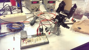
So I starting breadboarding a motor driver. The brain is an old PIC that was in a bin somewhere, and I tried to find some driving transistors that would work. I burned a couple, and then took stock of what components I had on hand.
There was really no transistors around that fit the bill. I measured these DC motors to run at a good speed at about 8.5v and 500mA,so the power requirements are not low, when you’re trying to use 3906 BJTs or whatever.

Breadboard H-Bridge


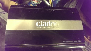
That day ended there. I thought about the problem for a few days, then I came back and grabbed a 200w amplifier from the recycling bin and pulled it apart.


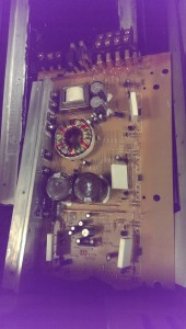
300W Amp Outside300W Amp Inside


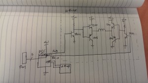
Inside it were 4 sets of 2SA1908 and 2SC5100 complementary BJTs. Perfect. Wired them up like so, and I have a gimbal driver.

Gimbal breadboard schematic

Now I need to incorporate all of the sensors.

First Burn

During my research on how others have handled the sparking circuit in an EDM, I’ve been fairly unimpressed. Off the top of my head, there was one 555-based pulsing EDM circuit, one purely analog circuit that was never built, and one hand modulated system attached to a drill press.

It’s hard to tell exactly what will make a winning design, so I’d rather not hamstring myself with fixed logic that may or may not be ideal. And for the first few iterations will almost certainly fall on the “not” side of that line.


What I’ve settled on (and indeed, what my education is in) is computer control. Small microcontrollers have gotten fast and cheap enough that there is very rarely a reason not to use them, other than bragging rights or very high volume manufacturing.


That’s a little bit unfortunate in some cases, but it’s great for this one.


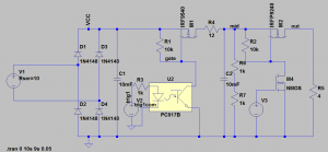
Here’s a first third draft of the circuit I’ll be using. I had a few false starts, but this one is the first one I actually (mostly) drew out, and it seems to work. I used two power supplies in series to get 60V and breadboarded it up. Not the final 80V supply, but close enough.

EDM SPICE

I only simulated the first stage (and with the wrong optocoupler!) but it proved the concept.


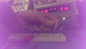
So I got my first burn last week to prove the concept! I tried to get a picture of the sparks, but it was tricky with my crappy phone camera. I was totally welding wires together, though, it was awesome. In theory, that shouldn’t even cause excess wear on my components or power supply. Everything is well within spec.

First Burn


I’m a little but worried about the speed of my components. I’d like to be able to get this pulsing in the 20ns range, but I’m pretty far away from that, I believe.

The two important components in this are the H11D3 optocouple and the IRF9540 P-Channel MOSFET.


According to the datasheet, the transistor has a rise time of 73ns, which right there blows my timing requirements. It has a turn-on delay of 16ns which also isn’t fantastic. That’s 100ns just for the transistor.


The optocoupler is worse, however. About 5 us. I’m not familiar enough with them to know if that’s a good value or not, but I’ll look at my options for rev 2.

Worth noting that this has a base connection, which doesn’t seem to make sense, given that the optical input is basically the base.

From here, though:

Click to access an3011.pdf

It looks like it’s to my advantage to use the base! It’s floating for now, but I’ll tweak the values to get to the most out of it when I have a scope on it.

Start small.

Other than wanting to spend very little money on this project, the scope of it is huge enough that I’ve been trying to use as many prebuilt components as possible.

If I have the majority of the project build with discrete, modular components, then I can start drilling down and replace the weakest links, one at a time.

Because the CNC portion is horribly complicated, and itself comprised of several parts (drive electronics, mechanical movements, control software, firmware), several weeks ago I made the decision to use a low-cost CNC platform. I mean “platform” in the sense that it’s designed as a starting point to hack, redesign, and improve.

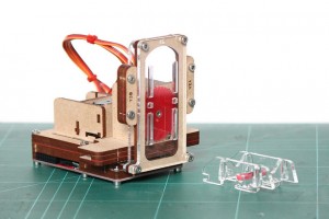
It’s called the Piccolo:

piccolo stock

It uses three (TINY!) servo motors, a bunch of laser cut gears and mounting plates, and some Processing-based software. Everything is open-source, and I don’t think they even sell any of the components themselves. They provide all of the files and expect people to make it on their own, which is kinda cool.

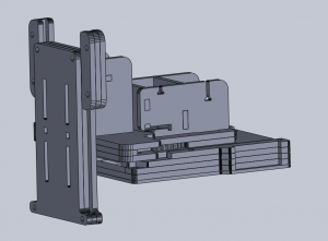
One thing I couldn’t find on their site anywhere was the work area. I needed dimensions of all of the parts to mount and design around this anyway, so a couple hours with their laser cutter files produced this:

piccolo model

Turns out all axis have a range of about 2.5 inches. That’s really tiny for a CNC platform, but definitely usable for making PCBs. At first, anyway. That double-ensures that this portion will eventually be replaced, probably with a CNC system of my own design. That will be fun, I am looking forward to it.

One note for future-self:

There is a decent chance that the sparking from my electrodes will cause enough interference to mess with my servos. If they get really jittery during a burn, I know exactly what is happening, and a redesign will happen sooner rather than later.

Working with the above files, I gathered together some more materials:

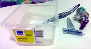
EDM Tank Supplies

A 12V oil pump($12) for the EDM fluid (more on this in a future post), a standard heavy duty door hinge($3), and a small plastic tank($0.89). The tank is a lot smaller in person than it looks.

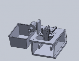
Putting it all together:

edm tank model 1

That’s a reasonably accurate mode of the tank on the left.

There’s also models of the Piccolo and the fuel pump that you can see there.

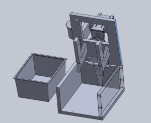
The rest of the frame is designed out of 1/2 inch MDF. The tank fits in the box, which can flip up like so:

edm tank model 2

And BAM. Hinges. The idea is that the whole mess can flip up for servicing, changing out the PCB, etc.

The PCB holders at the bottom might be changed a little before I build this, but the idea will stay the same. They’ll be submerged in the EDM fluid in the tank during operation. Afterwards, the top flips up, and those PCB holders are angled so that the oil drips back into the tank.

That should mitigate oil going everywhere somewhat. I still expect this to get messy.