Anatomy of a Pen

I’ve written recently about machining my own custom pen because, much like lamps, they are a “form over function” project where the end result can be gorgeous as well as useful. Aesthetically pleasing to everyone, not just techie people. And they don’t take up a lot of space!


Initially, my design for the first pen was sketched out in notebooks, and then modelled in CAD, then back to the notebooks when I was in the shop. This helped me get a general feel for what I wanted, but many style, material, and mechanical considerations had to be redesigned on the fly as I found techniques that didn’t work, and others that did.

A lot of the dimensions of final product came down to how they felt in my hands, as I was building. That’s fine for a one-off, but I’d kinda like to parameterize basic measurements so that I have some guidelines on what works for future pens.


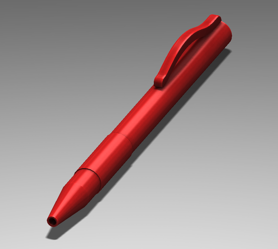
So here’s a pretty generic pen, modeled in Solidworks.


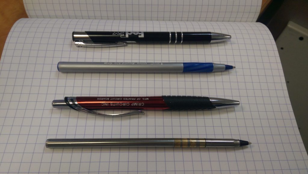
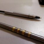
Here are a few pens I had within arm’s reach.


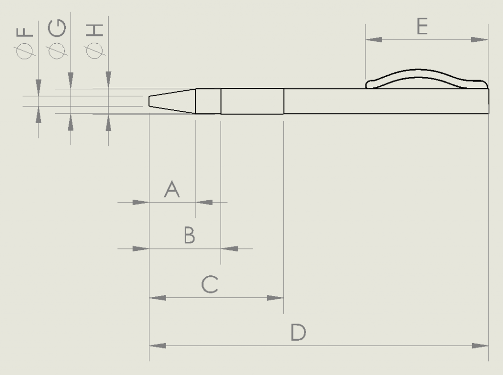
Starting at the top, I named these 1-4, and made some basic measurements based on the generic model:


Now I’ve got a good baseline for what makes a comfortable writing utensil, a recommendation for critical dimensions to stay within, and some language (or at least letters) to be able to intelligently discuss the anatomy of a pen.

Sure, we’re brute-forcing, but what’s the rush?

Ironically, in the process of writing a really fast implementation of the WPA2 encryption scheme, it was necessary (or at least easier) to first write a really slow implementation.

Here is my wpa2slow Python module.

To be fair, the actual speed at which this hashes isn’t the point. The point is that I have an entirely native Python implementation of how the entire WPA2 algorithm works, with an emphasis on code being clean, easy to read, and forgoing any speed optimisations that hinder legibility. Judging from the quantity of misinformation I’ve seen while researching this topic, someone will find this project useful. A lot of people have been having trouble trying to fit all the pieces together, over the years.

At first, I included the pieces as mock objects for unit testing. Each of the pieces (SHA1, HMAC, PBKDF2, etc) were built up over a period of several months, vaguely mimicking the interface format of equivalent existing hashlib libraries. Unfortunately, all of the standard Python hash libraries are really inconsistent!

For example, to hash a string with SHA1, I’d use:

output = hashlib.sha1(str)

Makes sense. But to then hash it with HMAC-SHA1, I’d do:

output = hmac.new(secret, value, hashlib.sha1)

Which is pretty weird, in this context. It makes more sense when you realise that HMAC can work with multiple sub-algorithms (commonly SHA1 or MD5), and you can go multiple rounds with adding more salt. That’s not the case in my implementation, however, so copying the format was a mistake.

One thing that rests solely on my shoulders is the massive amount of debugging information, hacky fixes, and generally poor code I’d written while focusing on an entirely different problem.

If I had written it cleanly from the beginning, it would have been a lot less work, that was silly of me.


Anyway. It’s pretty decent now. Check it out, read the docs, or install it!

pip install wpa2slow

ReacTick R1.5

Prototyping aw yeah.


After the first version of my LCD widgets, there were some things that I was planning on changing for the next respin. R1 just to get some hardware in my hands and start writing code. This next one is all about the cleanup.


The last version of R1 is here on GitHub. It works… Poorly. The code in the test folder is stuff to help me prototype, before I got to a working model. Originally, I tried writing an LCD driver in Python for the Raspberry Pi GPIO, but the output seemed super unreliable. Instead of taking the time to troubleshoot why, it was faster to port that code onto a PIC dev board, which worked great.

Once I had a known-good LCD (using the shift register), I finished soldering up the rest of the board and tried to bring up the whole board. It never quite worked properly, and here’s why!

When I was first drawing my schematic, the most common ESP8266 module was the ESP-12. Right around that time, November of 2015, the ESP-12E had just come out, with a bunch of extra pins. No one knew much about this at the time, but the conventional wisdom suggested that it was safe to include them in my design, allowing me to get away without using an additional microcontroller. Turns out these extra pins are associated with the flash memory, and using them willy nilly causes strange reset issues. Guess what kept happening when I was trying to test my fully populated board?

So before a complete rethink was in the cards, here was the original plan for revision 2:

  • The LCD has two little mounting tabs on the sides. An appropriately sized via to accommodate them will make the LCD fit better and prevent wobble
  • One of those mounting holes will interfere with the switches. Move them somewhere else. Specifically on one of the short edges, because the current location causes damage to the LCD when the buttons are pressed while the screen is face down on a table
  • Silkscreen for momentary switches to include functions (RST / PROG)
  • Add in the clever circuit that the NodeMCU group uses to enable button-less programming
  • Remove all unnecessary resistors:
    • R7 connected to LCD_RST
    • R10 connected to LCD_RS
  • Change LEDs to 0805 or something similar. I’m using 3528s, and they are huge and super bright and look out-of-place
  • Change user-settable LED to connect to a pin that is not GPIO16. Apparently some manufacturers (not mine) connect it internally to the ESP8266 reset pin
  • Change all the SIPO shift register pins from bit-banging to use the ESP serial ports – Should be faster, and allows me to…
  • Change requirements from an ESP-12E module to just and ESP-12, which has fewer pins
  • Break out extra ESP pins to some unpopulated pads for future hacking
  • Break out LCD touchscreen pins for future hacking
  • Add more testpoints for debugging (and future hacking)
  • Big decoupling cap


Some of these ended up making it in, but the new system design deprecated other points. So what’s new in R2? Stay tuned to find out!

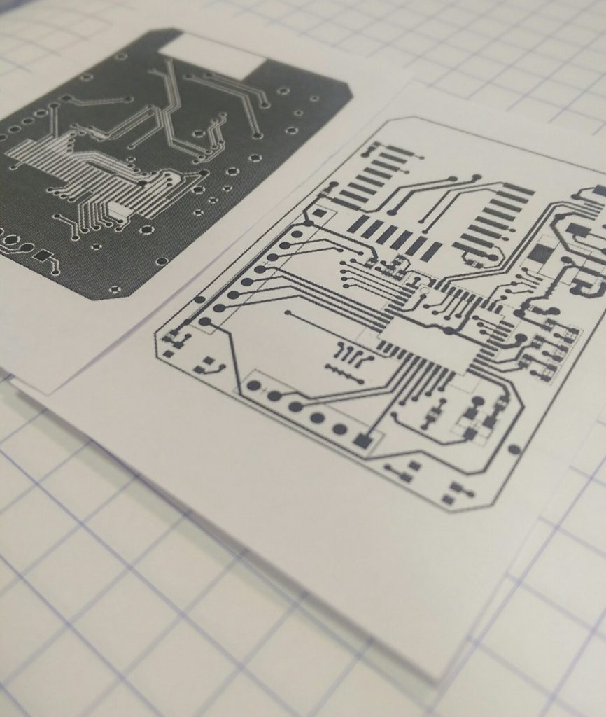
R2 Paper

A Quick Re-Intro to the Lathe

As my current favourite project is primarily a software one, I really need something on the side to keep my hands busy.


So I opted to do a small, easy metal lathe project. You know how those go, right?

It ended up taking over 40 hours, mostly because I am bad at this. But I learned a lot!


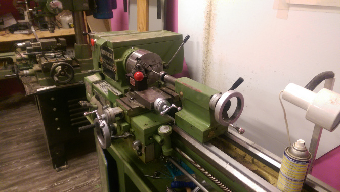
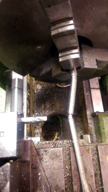
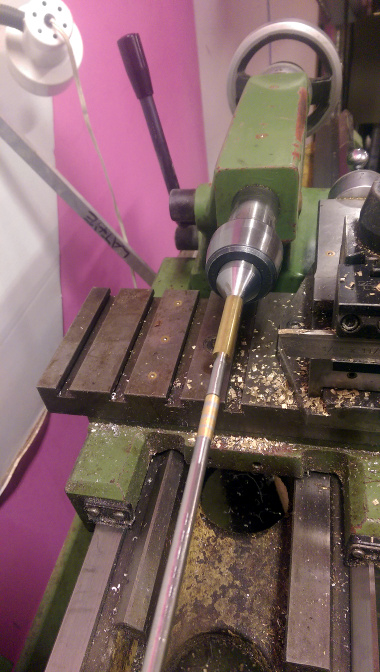
Here is the excellent old-school lathe I used:

pen1

Initially, this was going to be all brass, but Metal Supermarket doesn’t really carry a lot of red metals. Metal Supermarket is awesome, but pretty much the only stuff they carry is solid brass rod. It’s difficult to get a concentric hole through the entire length required by a pen, so that doesn’t work too well.

While browsing their stock, though, I found some gorgeous thick-walled stainless steel tube stock. Had to buy it.


I started out without a complete plan of what I was trying to do, and it’s clear that I was just playing around with shapes.

pen2

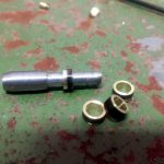
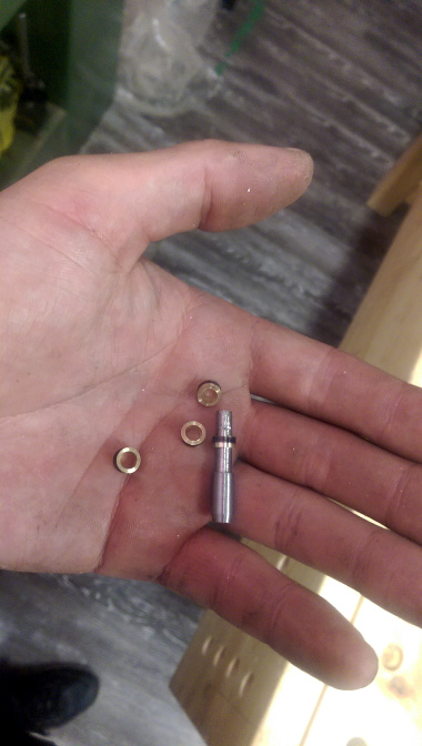
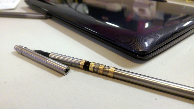
So I decided I liked that, parted off the left side, and machined some brass rings to go around the grip as extra bling.

You can see the scales I was working at, this all ended up being pretty precise work. Our lathe is a little large to comfortably get in to close features with the tailstock in use, but it’s still possible when you’re careful.

pen5

This piece had no way to effectively join it to the other side of the pen due to lack of forethought, so it had to be scrapped.

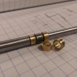
The next version was a little bit better, and shows the steel-brass-steel ring pattern, and kinda how everything fits together.

But then, one of the biggest takeaways I learned on this project is that working with stainless steel suuuuuuucks.

pen9

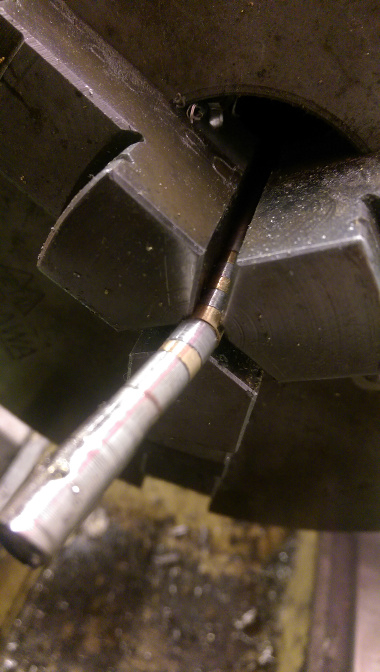
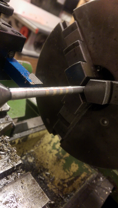
It’s really malleable, and is able to bend with low forces, even less than an inch away from where it’s being held.

Due to the high carbon content, it’s super hard on the tools and required frequent resharpening. When the tools are dull, the metal goes straw-coloured due to heat treating really quickly, and gets even harder.

So here’s attempt number three. I’m at about thirty hours by now, but getting faster after every failure.

pen10

I’ve attempted to fix everything together with superglue for machining, but there are issues with that. I’ve seen people use superglue for all sorts of workpiece holding in brass, but brass is really soft and easy to work with. While trying it with steel, the forces are much greater, in addition to the steel getting warm and melting the glue. Basically an exercise in frustration and not really worth it (for steel).

Nevertheless, regluing often and working slowly eventually starts to get results.


pen11


Until…

pen12

Attempt number four used a separate aluminum piece that I machined into a very thin-walled tube – about one quarter millimetre walls – instead of a single steel piece, because it’s much easier to work with.

pen13

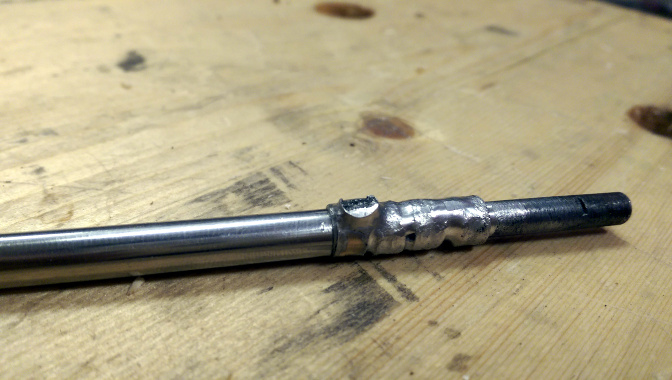
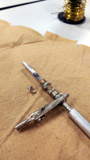
Abandoning superglue, I tried using silver solder. This was a risky prospect, because aluminum forms oxide layers that don’t adhere well to solder, and stainless steel just doesn’t wick until very high heats. So I used a MAPP gas torch, liquid flux, and silver solder, which resulted in…

pen14

My brass rings melted right off the tube. Was not expecting that.


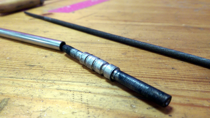
Okay, attempt number five. This was a tube I machined out of mild steel with the brass rings, and only silver solder between them instead of alternating with steel.

pen15

As opposed to stainless steel, mild steel was really easy to work with and soldered to well. It oxidises, though, not acceptable for anything on the outside of the pen. So it needs a sheath on either end.

pen16

And then roughing it out. Superglue works fine for the final steps, because there are no cutting forces trying to tear it apart.

pen17

Filing and finishing it. So much filing. Part of the reason this project took so long is that between each of these steps, there’s one or two hours of filing to make all of my interference fits work.

pen18

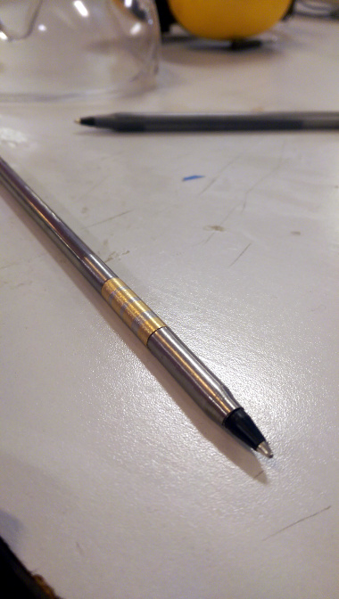
Afterwards, I sanded from 180 grit all the way up to 600 and then emery paper. It was mirror finish by the end, and with a little bit of polyurethane varnish used to seal it all in.

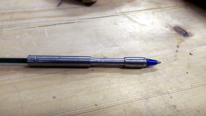
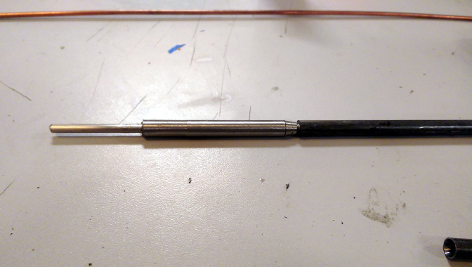
As you can see, the idea is to hold a standard Bic pen cartridge, nothing fancy. Next pen can be more complicated, I wanted this one done quickly. Things I learned:

  • Stainless steel is The Worst
  • Silver solder actually looks great and is easy to work with
  • Stainless steel is so bad
  • Those Youtube videos where they lightly touch the piece with an emery board after they finish machining? They’re cutting like an hour minimum of work out of the video
  • I’m never working with stainless steel again

I’m done with this project, but there are definitely some things I’m not totally happy with, to be fixed for the next one:

  • I built a little pocket clip using spring steel and hammers , but never ended up putting it on
  • There are tool marks on the front portion
  • The very front edges has a little lip from the mandrel deforming it
  • I didn’t let the varnish set properly, so it’s coming off a little
  • There should be some tactile difference where the grip is, it turns out this pen is a little hard to pick up and use without looking at it.

Unpacking WPA2

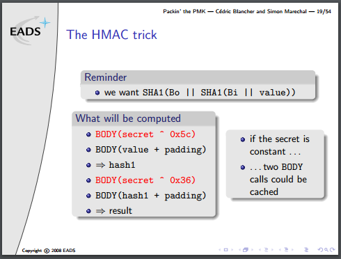
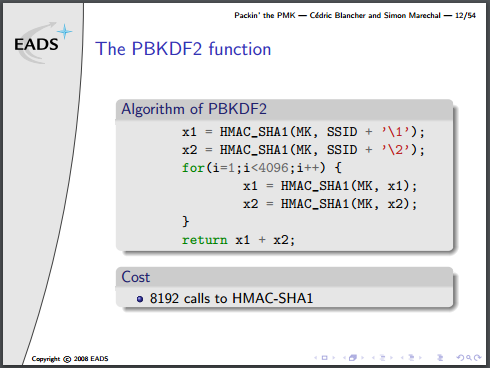
As discussed in a previous article, WPA2 encryption is comprised of three different algorithms layered on top of each other. I went over them in a very brief overview, so here is a more in-depth discussion on how I optimised and implemented them on an FPGA.

Also linked in that previous article, it’s worth going back and reading this presentation again. It really is a great overview of each of the three algorithms and how they fit together, without muddying the waters with the low-level details.

Disclaimer: This is my process for understanding and breaking them down. I will be using non-standard terminology, and there are certainly other ways of internalising these algorithms. My methods aren’t the only methods.

The lowest building block, SHA1, has four distinct sections stages of note: Load, Process Load, Process Buffer, and Output.

In a completely linear implementation, it would look like this:

SHA1 Linear

I’m assuming a bus width of 32 bits. The input/output blocks on the end are fixed in size, and cannot overlap. Not if we want to maintain half-duplex compatibility with the parent device. That may or may not be important, but it sure does simplify the implementation for now. 165 clock cycles total.

We have a little more wiggle room with the red blocks. Because the buffer can be processed as it is getting populated by the Process Load stage, we can merge them. Extrapolated, and using the input/output as the bottleneck, we come up with this:

SHA1 Parallel (2)


Notice that there’s still only one green section running at any single point along the horizontal. That’s the critical path, and dictates how many parallel operations we want to run at once.

It works out to 106 clock cycles for one cycle, assuming we run 5 hashes in parallel. So, 22 clocks per hash. Way better.

hmacpseudo

The next block up, the HMAC function, contains two SHA1 functions, which is sort of annoying. The second/outer call is also dependent on the output of the first/inner one, so I can’t parallelise that at all. To fill up the 5 SHA1 operations I have going at a time, I must also be running 5 separate HMAC operations.

There is one optimisation to be done, though, mentioned in the presentation. It’s not obvious how it’s useful in a concurrent environment, but bear with me.

Part of the algorithm requires two buffers to contain the ‘secret’ portion of the HMAC input, padded with 0x36 or 0x5c up to 64 bytes. The parent algorithm, PBKDF2, iterates two HMAC functions, 4092 times, all with the same secret variable. That can be calculated once and used for the entire loop.

If everything is done in parallel, then one would expect that the calculation could be done on-the-fly with little to no penalty. When you consider that each round of SHA1 is 64 bytes, however, you realise that a padded 64-byte input message, followed by the ‘secret’ variable requires two complete rounds of the SHA1 function to come up with the final result. But the first round of SHA1 results in the same output, every time, and can be precalculated. This turns the HMAC algo from what is effectively four SHA1 operations into only two.


pbkdf2pseudo


Note that they’ve actually written this algorithm incorrectly, there is an additional XOR to combine each stage of x1/x2 into a final result, but no matter for this discussion.

The PBKDF2 part is by far the most expensive step, because the area of most FPGAs will be too small to unroll 8192 copies of the SHA1 algorithm (which requires minimum (80 words * 4 bytes * 8 bits = 2560) bits of buffer space). One more optimization could be done, given the right conditions, and it’s a doozy:

The final, very last operation in the whole mess is to append x2 to x1. No hashing after that. That means the final output is two groups of 5 words (40 bytes total). This is the Pairwise Master Key. It is statistically unlikely that the first 20 bytes will be correct, but the second group would be wrong. This means that if we have the PMK and only need to verify it, we can do these calculations with exactly half the silicon area, or twice the speed.

Unfortunately, in this particular use-case we don’t have it, but it’s a great trick to keep up our sleeve.


So what do we have in this use-case?


We’ve gone from the wifi SSID and passphrase, known as the master key (MK), and from that, generated the Pre-Shared Key (PSK), which is known as the Pairwise Master Key in this particular implementation of the PBKDF2 algorithm.

To verify the PMK against the passphrase, something called the “Pairwise Key Expansion” is calculated. From the captured WPA2 packets, we have a few variables: client MAC address, AP MAC address, client nonce, AP nonce, and the Message Integrity Check (MIC), packet body.

The first four variables, along with the PMK get combined together in kind of an annoying way, and then compared against the MIC.

They just call it the pseudo-random function (PRF), and it goes kinda like this:

a = "Pairwise key expansion";
b = min(APMac, CMac) . max(APMac, CMac) . \
    min(APNonce, CNonce) . max(APNonce, CNonce);
r = "";
for(i = 0; i < 4; i++) {
    r = r . HMAC_SHA1(PMK, a . "\0" . b . chr(i));
}
return r[0:64];


Yeah, the actual string is used in the PRF.

This gives us the Pairwise Temporal Key (PTK), which is then combined with part of the (encrypted) body of the packet we captured:


mic = HMAC_SHA1(ptk[0:16], data[60:121]);


And then compare this to the MIC we’ve already captured! Easy, right?

No! It’s a huge pain and would add another HMAC_SHA1 block that we don’t really have room for. This will probably be implemented on the microcontroller firmware or the host software of my system.

USB Side-Project

Sometimes I get a little bit inspired by things on the internet. The internet isn’t all bad.


Here are some projects, pictures, or schematics that I like:

http://old.bennahill.com/tsunami/

http://www.piclist.com/techref/io/usb/pcbmaleconn.htm

http://vonkonow.com/wordpress/2012/03/usbserial-pcb/

http://dlnmh9ip6v2uc.cloudfront.net/datasheets/Prototyping/PowerCell-v13.pdf

(That’s mostly a reference for me, for later)


Pretty regularly, I have need of a cheap microcontroller that does one thing only, like output a stepper motor’s step sequence. It would be nice to have a pile of these, and be able to leave them in place, price being insignificant.


A pretty obvious candidate is the PIC18F14K50. It’s an older PIC that costs about $1.50, has a very small package, and speaks USB. I had also planned to draw a USB card edge connector. The advantage of that is that it’s easy (no solder required!), cheap (minus the costs of a slightly longer PCB), and compact. The cons are that it requires an ENIG gold plated finish to prevent contact oxidization, and the FR4 thickness needs to be 2mm, which is not standard, although not super unusual, either.


I’ll probably still do that, eventually, but first I got distracted by opening up a USB flashdrive.


Then this happened:


So I sent it off. It’s a hair larger than the original flashdrive PCB because of the programming headers, but it fits.

USB Thing

I used the PIC18F14K50 because I have a pile of them, but if I were to go for an even smaller package, I could fit a flash memory chip on the other side, like the original. That’s a great pathway to a flashdrive that writes a rootkit on-the-fly to data as it gets stored, for example. Scary stuff, and it doesn’t even seem that hard.

A flash memory chip is even pretty bulky, for what it is. By replacing it with a microSD card, there is even more space for other junk. Like using an ESP8266EX for the microcontroller, and drawing a small wifi antenna on the PCB.


There are so many side channels for this project, I don’t even know where to start.

In the meantime, I’ve spun this off into it’s own repo, here.

There’s a quick LED-blink program, but the real fun is in the “HID” projects.


Note the pogo pins I jammed into my PicKit for programming. The slot quite nicely into the programming header, while the board is being powered over USB.


When you plug this in, it appears to be a dud flashdrive. Doesn’t do anything. Until you forget about it and leave it in for ten minutes. At that point, it emulates a HID keyboard, and starts typing commands.

As this is just a test, it types “Windows-R->Notepad->Hello world!”, but it’s a great demonstration of the terrifying stuff you can do with literally 15 hours or less of work.


Keep in mind, I have never worked with USB hardware before. This stuff is not rocket science.


Don’t plug in unknown USB drives, folks!


Laser Cut Spice Racks

I’m still transferring my SolidWorks knowledge into Fusion 360, and definitely getting the hang of it.


Previously, I was having troubles mating parts properly, which totally makes sense. The way Fusion 360 and SolidWorks handle these concepts are the largest difference in workflow so far.


Where SolidWorks requires each “part” to be one object, and all parts must be added to an “assembly” for positioning and mating, Fusion 360 allows all of these to happen in one file. When a part is created, however it is called a “body” and must be turned into a “component” before repositioning or aligning it with other component. I’m not sure the benefit of this, but hey, that’s how it works. After a body has been turned into components, the “joint” command is analogous to SolidWork’s “mates”. They’re a little bit more finicky, but they work.


shelf v25


Here’s the latest experiment. Once again, this is almost entirely parametric. I had an idea to store all of my surface mount components in vials, and this is a pretty ideal way to stack them up. I realised about halfway through that, while designing a vial storage rack, it’s basically a spice rack.

One of the problems with this, is that over time I’ll be adding to it. Next time I need to laser cut some more, am I going to be able to find the same size of container? Am I going to be able to use the same size of material? What if I want a different sized rack to fit into a particular spot? Parametric!

There are a lot of variables in this one. Fortunately, most don’t have to be touched, usually.

In adapting these for different container size, the important variables are shelf_numVials and all of the vial_ parameters.


For the larger ones I got from the dollar store, they are:

vial_height = 48.75 – 11.5mm

vial_diameter = 27.5mm

vial_lidheight = 11.5mm

vial_lidDiameter = 31.25mm

These are unlikely to be available anywhere else.


The smaller ones from China are:

vial_height = 49 – 9mm

vial_diameter = 10.75mm

vial_lidheight = 9mm

vial_lidDiameter = 12.5mm

These are orange-lidded, 1.5mL plastic test tubes from AliExpress.


I’m now at revision 3 – The first one I cut sagged a little more than I would have liked, so I designed in a back piece at a right angle to straighten everything up.

Spice Rack R1


That worked, and stacking R2 on top of the first version pushes the ends out – effectively pulling it straight.


All of my files are available on GitHub here, or through Autodesk’s weird cloud platform.

Here’s an older version showing them stack:

http://a360.co/1X4LDGb


Here’s the latest version with all the bells and whistles:

http://a360.co/21Q52Bq

This is the one you want, if you’re planning on doing something similar.

Reconfigurable CNC platform

I’ve got a big thing about building stuff in a modular way.


So I installed Fusion 360 yesterday, and I’m pretty impressed. Fusion 360 is a new SolidWorks competitor by Autodesk. Basically a $6k-8k CAD package, released free for hobbyists or businesses making less than $100,000 a year. That’s quite a hook.

Especially considering how good it is already. It’s not quite at par with SW, but the feel is very similar, and I can see it eventually being a strong contender. Plus, you know, free.


The parametric engine is also very good. I’ve been meaning to build a CoreXY platform for a long time. It’s an open source belt-driven CNC platform with balanced forces in the X and Y axis, an excellent build-area / platform-size ratio, and parts that are amenable to laser cutting. There isn’t a specific project it will go with, but you never know when you need to drop a CNC system into something. CNC everything!

The idea behind building it is that I’d like to be able to design and build a platform to conform to whatever my requirements for a specific project within about a day or so. There are a few major variables that could potentially change:

  • Motors
  • Belts / pulleys
  • Precision rod
  • Material thickness

I’ve already purchased belt and pulleys ($10 for the cheapest GT2 belt, $10 for matching pulleys), and ideally, I’d be able to use the rest of those common items that I have kicking around, or can scavenge easily.

So I redesigned the CoreXY platform entirely using variables and formulae. Based on the waterjet cut CoreXY. Here’s a list of the variables that you need for a CNC, apparently:

CoreXY VariablesThat’ll change a little as I continue tweaking.

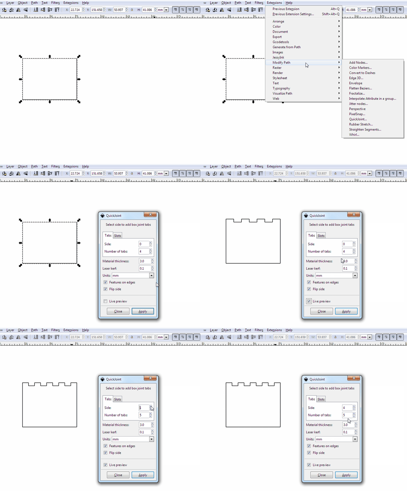
All other measurements are derived from those. Now when I need a new system, I take stock of the motors, sheet material, and so on, and enter the values into the window. A laser cutter file magically appears on the other end.

Here’s my project. It’s definitely subject to change. Accounting for laser cutter kerf is on the roadmap, and waterjet cutting would be good to design for, too, although I’m not super familiar with the constraints on that.


The files are located in the cloud right here.


One thing that I had problems with, is that Fusion 360 is not capable of reading parameters from subassemblies or parent assemblies. I had to copy the same set of variables to all of my parts, which is pretty annoying. Some internetting says that this feature will be implemented Real Soon Now(tm), as of 2014.


A good help for that was an add-in called ParameterIO. It doesn’t work out of the box, though, there is a bug because of the dimensionless quantities in linear patterns.

I had to edit line 219 of:
C:\Users\Jarrett\AppData\Roaming\Autodesk\ApplicationPlugins\ParameterIO.bundle\ContentsParameterIO.py

To say this:

unit = ' '
 try:
     unit = _param.unit
 except:
     unit = 'null'
 result = result + _param.name + "," + unit + "," + _param.expression + "," + _param.comment + "\n"
 

(Full file here for easier copying.)


That allows you to export all of the user parameters, and also the model parameters as a CSV file. The same bug causes problems when you try and import!

Fortunately you can delete the second half of the CSV file before importing, because the model parameters are a useless thing for unrelated parts.

An add-in to automagically inherent all parameters from parent assemblies would be awesome, and fairly straightforward, from the looks of things.

Maybe this feature already exists and I just haven’t found it, or maybe I will have to work on it when I’m done the X axis of this thing.

I don’t lamp well


That was a long “next month”. A recap is in order. This post chronicles the long descent into complete and utter apathy.


In September 2014, I made some sketches for a lamp I wanted to build. The intent was to use the glass plate from a desktop scanner as the light diffuser, and laser etch a fractal pattern onto it to create a frosted effect, instead of being optically clear.

Here is a test piece I did, with a laser cutter and an image found off the internet.


The results were pretty fantastic. Fine details get lost, because it looks like the mode of operation is the laser heating up enough of the glass to chip off a small chunk before moving on. And so on, for the entire image. It creates great looking, even optical diffusion, though.


For another test, I decided to design and build a similar, but smaller lamp. Glass scanner beds are a limited supply. Using a glass tile I found at a craft store, I designed an arm to hold it onto a wall, a few centimetres away from a PCB containing some high power LEDs.


The initial model and 3D print is shown on my previous post.

Here is the final version, with some corrected measurements and better mounting point.

Lamp print


And the PCB arrived shortly after the last post.


Lamp PCB

Oops!

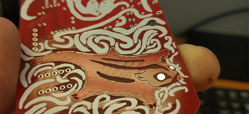
That’s mistake number one. Everything was intended to be clean and white, but I guess I forgot to change the soldermask from the default DirtyPCBs red. It’s not the end of the world. This is a prototype of a prototype, after all.


The first board was populated, and then the lamp languished for a year and a half.


Recently, I found it buried in a locker and tried plugging it in for the first time. With no prior consultation to documentation, I tried it on a bench power supply, starting at 5v. Nothing happened, so I turned it up to 10. At 15v, the semiconductor on the board released some smoke and glowed red for a few minutes.

Nope!


Back to the docs, I read that I had used an adjustable 5v boost converter, so that solved that.

I soldered up another board (I had two spares of the IC), including the DC barrel jack this time, and plugged it in again. Turns out I had the wrong polarity!

No smoke, but some troubleshooting proved that I had definitely fried the chip.


This was pretty much the limit of how much I cared, so I did what anyone would do:

I jumped over the active parts of the circuit with a power resistor, and ran the LEDs directly from a 19v laptop power supply.


Job done!

Next time I’ll build in some more safety factor.

Additionally, looking at the lamp from the side is really really bright because of the bare 1W LEDs. I kinda planned for this and put some slots in the side of the base for some acrylic sheets, but I’m quite done with this design.

Snap-on Desktop Widgets

And now, for my next trick, I’m going to manufacture a million tiny monitor widgets to snap onto your big monitors to monitor your widgets.


Still with me?


This is a project with many parts, but I will only get in to one phase on this log.
 

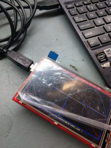
I’m hooking up an ESP8266 WiFi module to an inexpensive TFT LCD. The idea is to have an internet-connected, smaller-than-credit-card sized screen that displays one thing, and one thing only.

Some use-cases could be the two-day weather forecast, a slideshow picture-frame, or a graph of the current price of Bitcoin. Things that don’t require more than a couple changes per second, and don’t warrant using up real estate on a main monitor when work needs to get done.

The system design is actually really simple. A mini-USB connector is feeding power to a 3.3v linear regulator, and data to a USB-UART bridge. The bridge is able to program the ESP8266 via USB to a host computer, but that is not required for general operation. A standard cellphone charger plugged into the USB connector for power is fine. The WiFi module connects to an Access Point periodically and grabs a static image from a website.

This image is then fed to the LCD. That’s it. That’s all it does. I’ve gotten the BoM cost down to around $8 each, so it’s reasonable to have a lot of them on a desk, displaying various bits of data.


The hardware files, including Gerbers, of revision 1 are here. There are also folders for the firmware, software, and test rig, but as of the time of writing, that is all very much a work in progress.

That link will soon be outdated, but I’ll tag the first revision as a “Release” in GitHub when I’ve got the different parts working.
As for next steps:

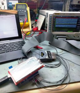
The LCD I’ve chosen is one of the cheapest ones I’ve found. It has a parallel data bus for communication, and I’ve used a 74HC595 serial-parallel chip to make it work with the ESP8266 module’s limited IO. I’m using an ESP-12E for reference, but trying to make it work with the original ESP-12 as a bonus.
Schematic

I think I can do some interesting things by replacing both the SIPO and the USB-UART bridge with a microcontroller. Things involving bootloaders, and things involving cross-monitor communication. Cool stuff.