As discussed in a previous article, WPA2 encryption is comprised of three different algorithms layered on top of each other. I went over them in a very brief overview, so here is a more in-depth discussion on how I optimised and implemented them on an FPGA.
Also linked in that previous article, it’s worth going back and reading this presentation again. It really is a great overview of each of the three algorithms and how they fit together, without muddying the waters with the low-level details.
Disclaimer: This is my process for understanding and breaking them down. I will be using non-standard terminology, and there are certainly other ways of internalising these algorithms. My methods aren’t the only methods.
The lowest building block, SHA1, has four distinct sections stages of note: Load, Process Load, Process Buffer, and Output.
In a completely linear implementation, it would look like this:

I’m assuming a bus width of 32 bits. The input/output blocks on the end are fixed in size, and cannot overlap. Not if we want to maintain half-duplex compatibility with the parent device. That may or may not be important, but it sure does simplify the implementation for now. 165 clock cycles total.
We have a little more wiggle room with the red blocks. Because the buffer can be processed as it is getting populated by the Process Load stage, we can merge them. Extrapolated, and using the input/output as the bottleneck, we come up with this:
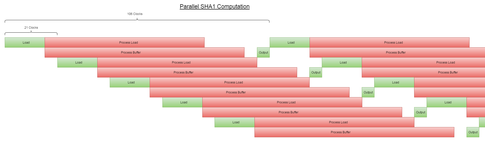
Notice that there’s still only one green section running at any single point along the horizontal. That’s the critical path, and dictates how many parallel operations we want to run at once.
It works out to 106 clock cycles for one cycle, assuming we run 5 hashes in parallel. So, 22 clocks per hash. Way better.
The next block up, the HMAC function, contains two SHA1 functions, which is sort of annoying. The second/outer call is also dependent on the output of the first/inner one, so I can’t parallelise that at all. To fill up the 5 SHA1 operations I have going at a time, I must also be running 5 separate HMAC operations.
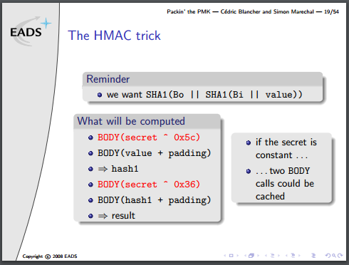
There is one optimisation to be done, though, mentioned in the presentation. It’s not obvious how it’s useful in a concurrent environment, but bear with me.
Part of the algorithm requires two buffers to contain the ‘secret’ portion of the HMAC input, padded with 0x36 or 0x5c up to 64 bytes. The parent algorithm, PBKDF2, iterates two HMAC functions, 4092 times, all with the same secret variable. That can be calculated once and used for the entire loop.
If everything is done in parallel, then one would expect that the calculation could be done on-the-fly with little to no penalty. When you consider that each round of SHA1 is 64 bytes, however, you realise that a padded 64-byte input message, followed by the ‘secret’ variable requires two complete rounds of the SHA1 function to come up with the final result. But the first round of SHA1 results in the same output, every time, and can be precalculated. This turns the HMAC algo from what is effectively four SHA1 operations into only two.
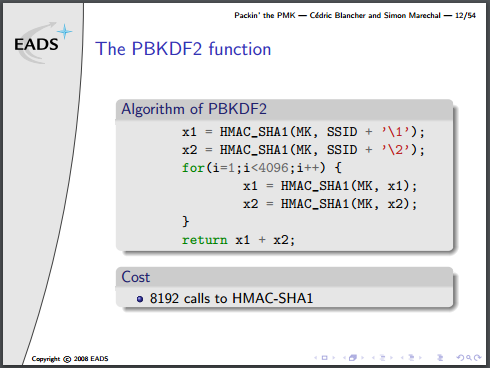
Note that they’ve actually written this algorithm incorrectly, there is an additional XOR to combine each stage of x1/x2 into a final result, but no matter for this discussion.
The PBKDF2 part is by far the most expensive step, because the area of most FPGAs will be too small to unroll 8192 copies of the SHA1 algorithm (which requires minimum (80 words * 4 bytes * 8 bits = 2560) bits of buffer space). One more optimization could be done, given the right conditions, and it’s a doozy:
The final, very last operation in the whole mess is to append x2 to x1. No hashing after that. That means the final output is two groups of 5 words (40 bytes total). This is the Pairwise Master Key. It is statistically unlikely that the first 20 bytes will be correct, but the second group would be wrong. This means that if we have the PMK and only need to verify it, we can do these calculations with exactly half the silicon area, or twice the speed.
Unfortunately, in this particular use-case we don’t have it, but it’s a great trick to keep up our sleeve.
So what do we have in this use-case?
We’ve gone from the wifi SSID and passphrase, known as the master key (MK), and from that, generated the Pre-Shared Key (PSK), which is known as the Pairwise Master Key in this particular implementation of the PBKDF2 algorithm.
To verify the PMK against the passphrase, something called the “Pairwise Key Expansion” is calculated. From the captured WPA2 packets, we have a few variables: client MAC address, AP MAC address, client nonce, AP nonce, and the Message Integrity Check (MIC), packet body.
The first four variables, along with the PMK get combined together in kind of an annoying way, and then compared against the MIC.
They just call it the pseudo-random function (PRF), and it goes kinda like this:
a = "Pairwise key expansion";
b = min(APMac, CMac) . max(APMac, CMac) . \
    min(APNonce, CNonce) . max(APNonce, CNonce);
r = "";
for(i = 0; i < 4; i++) {
    r = r . HMAC_SHA1(PMK, a . "\0" . b . chr(i));
}
return r[0:64];
Yeah, the actual string is used in the PRF.
This gives us the Pairwise Temporal Key (PTK), which is then combined with part of the (encrypted) body of the packet we captured:
mic = HMAC_SHA1(ptk[0:16], data[60:121]);
And then compare this to the MIC we’ve already captured! Easy, right?
No! It’s a huge pain and would add another HMAC_SHA1 block that we don’t really have room for. This will probably be implemented on the microcontroller firmware or the host software of my system.