
During my research on how others have handled the sparking circuit in an EDM, I’ve been fairly unimpressed. Off the top of my head, there was one 555-based pulsing EDM circuit, one purely analog circuit that was never built, and one hand modulated system attached to a drill press.
It’s hard to tell exactly what will make a winning design, so I’d rather not hamstring myself with fixed logic that may or may not be ideal. And for the first few iterations will almost certainly fall on the “not” side of that line.
What I’ve settled on (and indeed, what my education is in) is computer control. Small microcontrollers have gotten fast and cheap enough that there is very rarely a reason not to use them, other than bragging rights or very high volume manufacturing.
That’s a little bit unfortunate in some cases, but it’s great for this one.
Here’s a first third draft of the circuit I’ll be using. I had a few false starts, but this one is the first one I actually (mostly) drew out, and it seems to work. I used two power supplies in series to get 60V and breadboarded it up. Not the final 80V supply, but close enough.
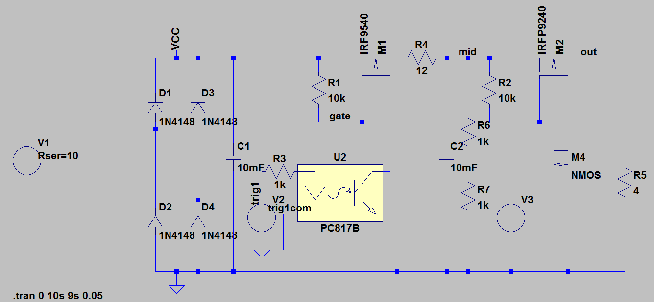
I only simulated the first stage (and with the wrong optocoupler!) but it proved the concept.
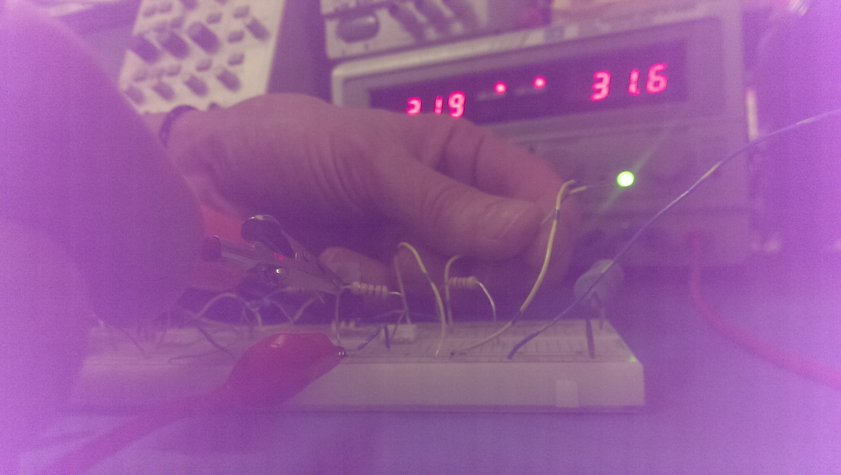
So I got my first burn last week to prove the concept! I tried to get a picture of the sparks, but it was tricky with my crappy phone camera. I was totally welding wires together, though, it was awesome. In theory, that shouldn’t even cause excess wear on my components or power supply. Everything is well within spec.
I’m a little but worried about the speed of my components. I’d like to be able to get this pulsing in the 20ns range, but I’m pretty far away from that, I believe.
The two important components in this are the H11D3 optocouple and the IRF9540 P-Channel MOSFET.
According to the datasheet, the transistor has a rise time of 73ns, which right there blows my timing requirements. It has a turn-on delay of 16ns which also isn’t fantastic. That’s 100ns just for the transistor.
The optocoupler is worse, however. About 5 us. I’m not familiar enough with them to know if that’s a good value or not, but I’ll look at my options for rev 2.
Worth noting that this has a base connection, which doesn’t seem to make sense, given that the optical input is basically the base.
From here, though:
It looks like it’s to my advantage to use the base! It’s floating for now, but I’ll tweak the values to get to the most out of it when I have a scope on it.