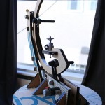
At this stage in the game, this project is on a clear path to completion, with no major revisions in sight. What I’d like to do is identify some issues that have made themselves apparent during the build and tweaking processes. Some are things that I would fix in the version 2, if one were to exist. Some I need to fix right now.
This also marks the end of the “let’s build something cool!” phase and into the “ugh. WHY isn’t this working?” phase. It’s a lot harder to stay interested in finishing, but I’m going to power through.
Here’s where I’m at:
- Limited rotation: any rotational movement that goes too far would tangle up cables that are driving the pitch gear motor. Everything in this system is designed to be battery-powered, so the obvious solution would be to mount the yaw motor on the rotating platform. That could mesh with an inside gear that’s been fixed to the base.
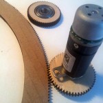
- Non-prime gears: this is one of the topics that have come up while doing ongoing research for what constitutes a “good” mechanical design. Generally, teeth shouldn’t continually mesh with exactly the same tooth and the opposing gear. That’s a good way to cause excess wear through dirt or inconsistancies in the the teeth hitting the same spot every time. To make sure that doesn’t happen, you want the gears to be co-prime. Right now, my two gear sizes have 55 teeth, and 280 teeth. That’s no good. Fortunately, 281 is prime, so that neatly solves that problem. The pitch gear doesn’t ever rotate all the way through, so that doesn’t fix the issue for those mates, but there’s nothing I can do about it, so why worry?
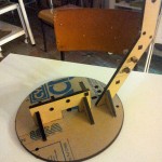
- Catching: the top gear(I’ve been calling it the pitch gear) catches up between the two gears providing support. When it gets caught, the gear likes to try and shove the rear support struts up and out of the base. This is the only problem(so far) that I haven’t foreseen. Fortunately, I was able to move that top support gear a little closer to the bottom portion using some holes that already existed. Anything less than 90 degrees seems to do the trick.
- Squeezed bearings: I used some flat washers on either sides of the bearings, but that still caused too much friction for them to rotate properly. I need to find some smaller nylon washers, or maybe flanged bearings.
- Wobbly base: the lower gear(I’ve been calling it the yaw gear) is mostly just sitting on a huge bolt that I had kicking around. I was hoping it would work, but no dice. It doesn’t quite. The gear wobbles around in relation to the base just enough to lose contact with the motor gear. When I can get some more laser cutting in, I’ll build another base with an additional cage around the bolt to provide more support.

