Quite a while ago, I did some experimenting with laser etching on glass. The intention was to backlight it and make a large lamp with some LEDs behind a large sheet of laser patterned and frosted glass.
Material costs pushed me towards scaling it way down and designing around a small glass tile that I picked up for a few cents. Just for an initial test, anyway.
The tile I chose is about 96mm², and just a hair under 7.3mm thick at the edges.
For the material acquisition side of things, I hunted for high power LEDs from Dealextreme, one of my favourite sites. They carried some 3W LEDs for a couple bucks, not bad. Then I checked Aliexpress. 1W LEDs were substantially cheaper, but I could only get them in quantities of 100. For $12. So I have some extras.
They measured out at around forward 3.2V. Current is about 120mA when the LEDs appear to be at max brightness. Theoretically they should go up to around 300mA, but this is good enough! I can’t see out of the centre of my vision!
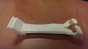
I’m not really a huge fan of 3D printers, but I really wanted to crank this thing out quickly and using one freed up any design limitations for this janky part I needed.
After six quick iterations, I came up with this:
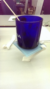
The angles turned out to be tricky to get right, but it worked out. Printed with support material on a Rostock MAX delta printer. The tile is held very securely with no fasteners, perfectly parallel to the base.
It even stands up!
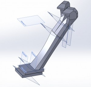
Bonus SolidWorks model view:
For the actual circuit design, I went with all surface mount for easier custom boards, and some free sample chips from TI. See! That program totally works for them, I’m locked into this design now. Actually, it was the best part for the job that I could find. The LM3410, which is a constant current, analog dimming, PWM output boost converter. Yeah, pretty cool.
I found an Eagle library part that had the same footprint as the LM3410, and then I used my standard “print footprints at 1:1” method to find suitable library parts for my Chinese LEDs and salvage-bin inductor with no datasheets.
Parts list:
- Inductor L1 – CDRH6D28-3R0NC – 3.0uH, 3.0A
- The datasheet reference designs used anywhere from 4-20uH inductors. Less inductance just means a little more ripple current, which should be okay.
- Schottkey Diode D1 – B260A-13, rated for 60V reverse voltage, 2A forward current.
- Zener Diode D2 – I don’t have this yet! Reverse voltage drop between 21-24V. Might have to stack a bunch in series.
- 1Ω R1, R3 – Two resistors, 1% tolerance, 1206, in parallel to make 0.5Ω
- 100Ω R2 – 5%, 0805 for voltage overload.
Here are the results of my circuit building:
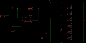
The schematic is mostly a reference from the datasheet. Max current and voltage limits are a dependent on switching speed, the inductor I used, and the heatsinking of parts, so no hard-and-fast rules. I stretched it to the most high-power LEDs I thought I could get away with. That’s 6. Six LEDs. Worst case scenario, I have to jump one or two of them if everything starts to burn. Best case scenario, I’ve got ten of these boards coming, a dozen inductors, a hundred LEDs, but only three LM3410s.
For this build, I’m trying out the new Dirt Cheap Dirty Board service run by Dangerous Prototypes. I’ve used OSH Park and iTead Studios before, so this will be a fun experiment.
Originally, I was going to etch my own board using a laser cutter and the spraypaint etch resist method. Unfortunately, I have (temporarily, I hope) lost access to the laser cutter. For $14, this seems like a reasonable alternative.
I will update in a month or so, when the PCBs get here.


