Archive for March 28, 2016

USB Side-Project

Sometimes I get a little bit inspired by things on the internet. The internet isn’t all bad.


Here are some projects, pictures, or schematics that I like:

http://old.bennahill.com/tsunami/

http://www.piclist.com/techref/io/usb/pcbmaleconn.htm

http://vonkonow.com/wordpress/2012/03/usbserial-pcb/

http://dlnmh9ip6v2uc.cloudfront.net/datasheets/Prototyping/PowerCell-v13.pdf

(That’s mostly a reference for me, for later)


Pretty regularly, I have need of a cheap microcontroller that does one thing only, like output a stepper motor’s step sequence. It would be nice to have a pile of these, and be able to leave them in place, price being insignificant.


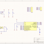
A pretty obvious candidate is the PIC18F14K50. It’s an older PIC that costs about $1.50, has a very small package, and speaks USB. I had also planned to draw a USB card edge connector. The advantage of that is that it’s easy (no solder required!), cheap (minus the costs of a slightly longer PCB), and compact. The cons are that it requires an ENIG gold plated finish to prevent contact oxidization, and the FR4 thickness needs to be 2mm, which is not standard, although not super unusual, either.


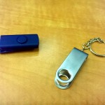
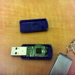
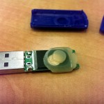
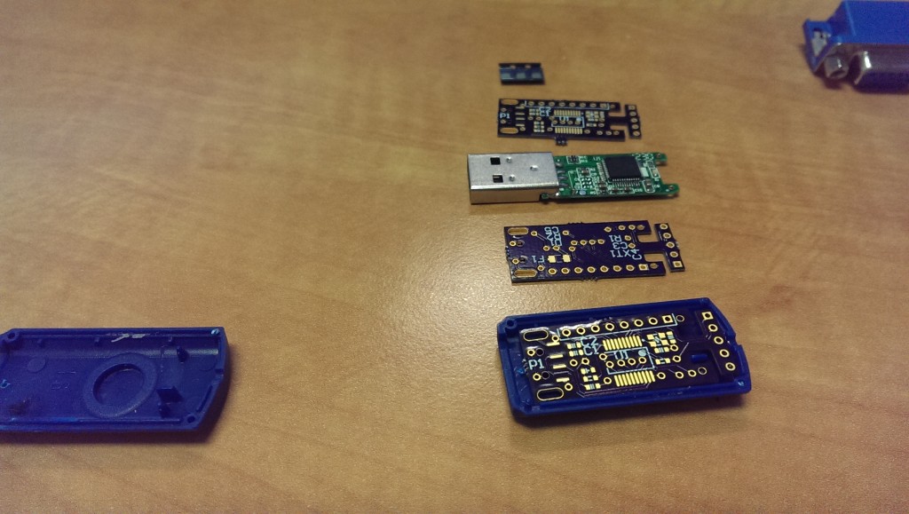
I’ll probably still do that, eventually, but first I got distracted by opening up a USB flashdrive.


Then this happened:


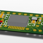
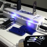
So I sent it off. It’s a hair larger than the original flashdrive PCB because of the programming headers, but it fits.

USB Thing

I used the PIC18F14K50 because I have a pile of them, but if I were to go for an even smaller package, I could fit a flash memory chip on the other side, like the original. That’s a great pathway to a flashdrive that writes a rootkit on-the-fly to data as it gets stored, for example. Scary stuff, and it doesn’t even seem that hard.

A flash memory chip is even pretty bulky, for what it is. By replacing it with a microSD card, there is even more space for other junk. Like using an ESP8266EX for the microcontroller, and drawing a small wifi antenna on the PCB.


There are so many side channels for this project, I don’t even know where to start.

In the meantime, I’ve spun this off into it’s own repo, here.

There’s a quick LED-blink program, but the real fun is in the “HID” projects.


Note the pogo pins I jammed into my PicKit for programming. The slot quite nicely into the programming header, while the board is being powered over USB.


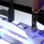
When you plug this in, it appears to be a dud flashdrive. Doesn’t do anything. Until you forget about it and leave it in for ten minutes. At that point, it emulates a HID keyboard, and starts typing commands.

As this is just a test, it types “Windows-R->Notepad->Hello world!”, but it’s a great demonstration of the terrifying stuff you can do with literally 15 hours or less of work.


Keep in mind, I have never worked with USB hardware before. This stuff is not rocket science.


Don’t plug in unknown USB drives, folks!


Laser Cut Spice Racks

I’m still transferring my SolidWorks knowledge into Fusion 360, and definitely getting the hang of it.


Previously, I was having troubles mating parts properly, which totally makes sense. The way Fusion 360 and SolidWorks handle these concepts are the largest difference in workflow so far.


Where SolidWorks requires each “part” to be one object, and all parts must be added to an “assembly” for positioning and mating, Fusion 360 allows all of these to happen in one file. When a part is created, however it is called a “body” and must be turned into a “component” before repositioning or aligning it with other component. I’m not sure the benefit of this, but hey, that’s how it works. After a body has been turned into components, the “joint” command is analogous to SolidWork’s “mates”. They’re a little bit more finicky, but they work.


shelf v25


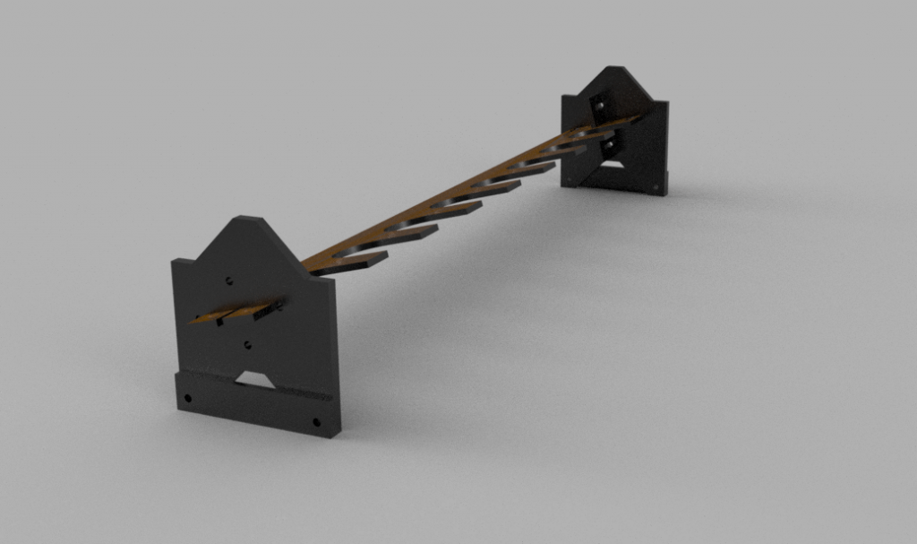
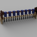
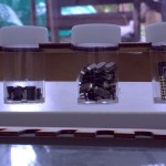
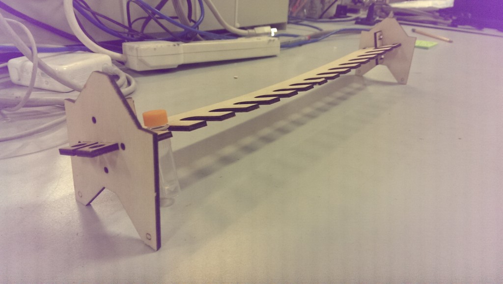
Here’s the latest experiment. Once again, this is almost entirely parametric. I had an idea to store all of my surface mount components in vials, and this is a pretty ideal way to stack them up. I realised about halfway through that, while designing a vial storage rack, it’s basically a spice rack.

One of the problems with this, is that over time I’ll be adding to it. Next time I need to laser cut some more, am I going to be able to find the same size of container? Am I going to be able to use the same size of material? What if I want a different sized rack to fit into a particular spot? Parametric!

There are a lot of variables in this one. Fortunately, most don’t have to be touched, usually.

In adapting these for different container size, the important variables are shelf_numVials and all of the vial_ parameters.


For the larger ones I got from the dollar store, they are:

vial_height = 48.75 – 11.5mm

vial_diameter = 27.5mm

vial_lidheight = 11.5mm

vial_lidDiameter = 31.25mm

These are unlikely to be available anywhere else.


The smaller ones from China are:

vial_height = 49 – 9mm

vial_diameter = 10.75mm

vial_lidheight = 9mm

vial_lidDiameter = 12.5mm

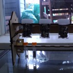
These are orange-lidded, 1.5mL plastic test tubes from AliExpress.


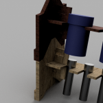
I’m now at revision 3 – The first one I cut sagged a little more than I would have liked, so I designed in a back piece at a right angle to straighten everything up.

Spice Rack R1


That worked, and stacking R2 on top of the first version pushes the ends out – effectively pulling it straight.


All of my files are available on GitHub here, or through Autodesk’s weird cloud platform.

Here’s an older version showing them stack:

http://a360.co/1X4LDGb


Here’s the latest version with all the bells and whistles:

http://a360.co/21Q52Bq

This is the one you want, if you’re planning on doing something similar.