I haven’t actually made an Internet of Things, thing, before now.
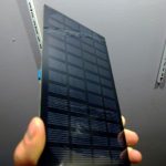
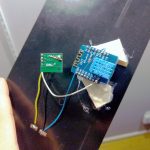
This is mostly just to throw some stuff together that I already had lying around. I’ve got a DHT11 temperature/humidity sensor, a WeMos D1 Mini ESP8266 dev board, a switch-mode power supply module, and a solar panel.
I turned it into an investigation on solar charging and ESP8266 power modes, while spending As Little Time As Humanly Possible on cleanliness, quality, or polish.
Yeah, this is super simple, and equally janky.
Threw it together in an hour with liberal amounts of hot glue.
Predictably, the solar panel was never able to supply enough juice to handle the startup current of the ESP8266, and it never sent any data points.
So phase 2 was to add a maximum power point tracker (MPPT) module feeding a Nokia battery as a reservoir.
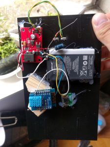
This one worked! It lasted about 18 hours until it died.
I’m sending data to Adafruit’s free(ish) MQTT platform, also for the same spend-as-little-time-possible reasons that this projectlet follows.
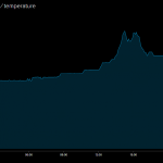
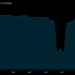
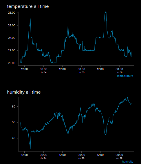
That spike/drop in temp/humidity is exactly the time period where I get direct sunlight in that window in May, so that’s neat.
Uptime is recorded in tens of seconds.
Now there are three problems left with this system:
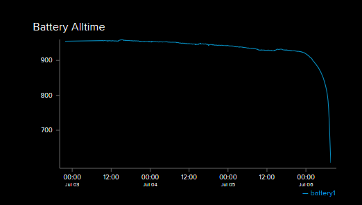
There’s no way to get an idea of battery charge until it dies.
The switch-mode power supply is a buck converter only, so as soon as the battery voltage goes below 3.3v (or maybe even above that), the output voltage cuts off, or possibly sags. I haven’t read the datasheet on this, so I don’t know or particularly care in this case.
Ideally, the solar panel can keep on top of the power usage. It doesn’t currently do this, partially because it’s sending too many datapoints (temperature does not swing wildly enough to justify once every ten seconds), and because I did not use proper deepsleep in my code. It’s just a while() loop that keeps the microcontroller chugging away at full bore.
So here’s the next update.
The ESP8266 has an ADC, but it’s limited to 1V max. With a max Lithium Ion voltage of 4.2V, I used a voltage divider of 1k in series with 4.7k and 10k in parallel. And then I realised that there was a built-in 220k/100k voltage divider designed for ~3.3v max, so I swapped mine out for a series resistor get into the 4.2v ballpark. This is all very approximate and I only had 680k resistors on hand, so 7 in parallel got me to 97k.
From my Switch Mode Tale, I happen to have a SMPS kicking around that is perfectly suited to the voltage ranges of the battery, too, so that goes in.
And, finally, the code changes were trivial. Another data point (battery) was added, and naive delay loops were changed to proper deep sleeps. This also required tying pin 16 to RST.
Still curious about battery lifetime, I commented the deep sleep mode out while running another test. This is still a while loop:
It lasted three days, and you can clearly see the spikes in temperature for a few hours in the afternoon as the sun hits the panel directly. And look at that lithium battery discharge curve!
I haven’t looked into my MPPT in detail, but that would likely be one of my next targets for investigation. I know it charges the batteries because I left it to do that for a few weeks in between tests, and the batteries were fully topped up each time. But I suspect it charges them really slowly, based on the lack of noticeable bump on the graph during sunny periods.
At this point, I took a brief hiatus from this side-project to do Important Things, and then it became autumn.
Using this power usage analysis, eventually, I will chip away at some of the possible optimisations. Some of the considerations described by Erik are obvious, but some of the others are quite clever. A mental shift to paying attention to the order in peripheral bring-up in a WiFi device is fun, and not something I’ve had to do much before. I will come back to this, for sure. Likely when I finish Rev 2 of my Sugar Glider board. As it stands, this side-project is in danger of going over my allotted five hours of actual build-time.

