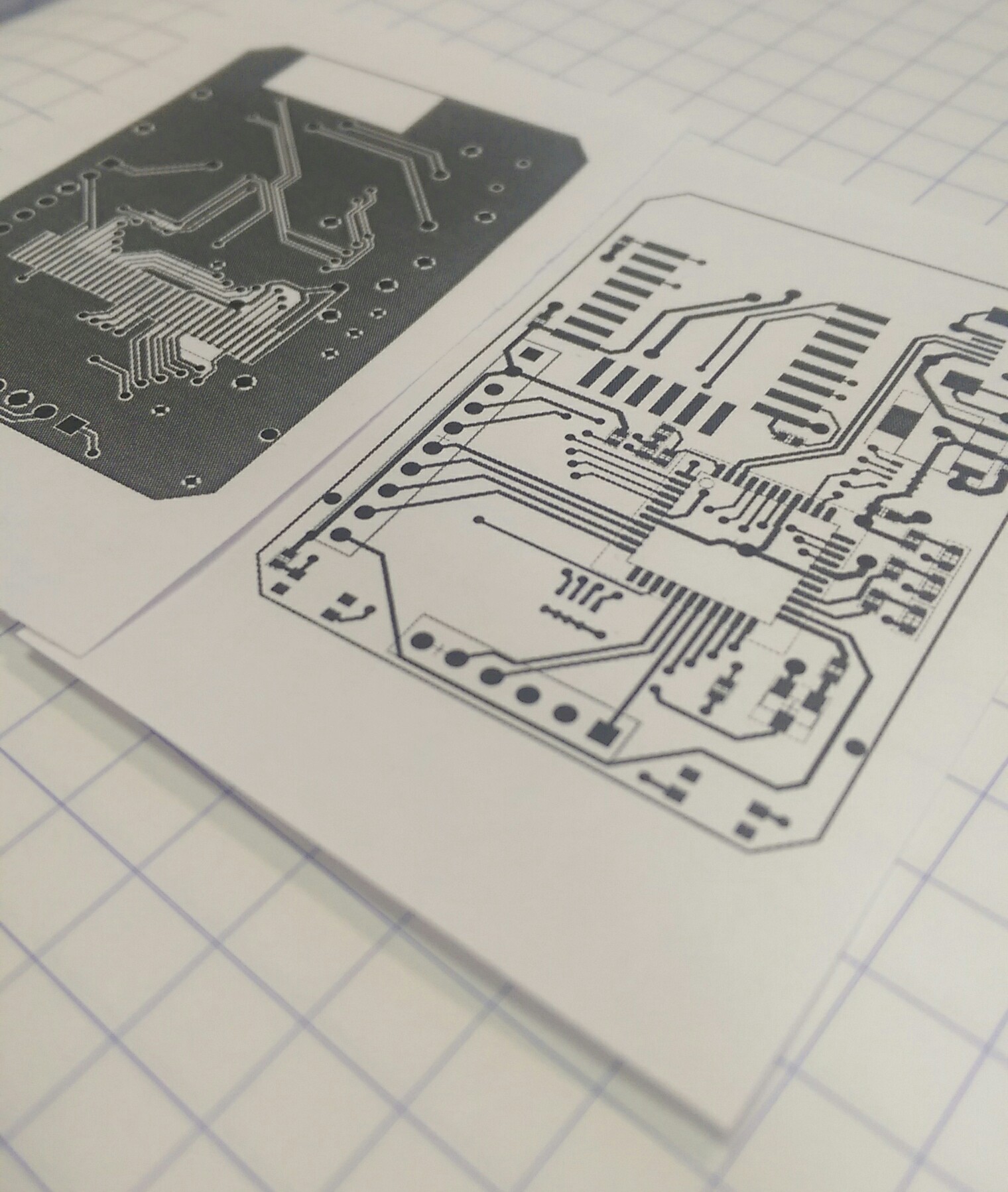
Prototyping aw yeah.
After the first version of my LCD widgets, there were some things that I was planning on changing for the next respin. R1 just to get some hardware in my hands and start writing code. This next one is all about the cleanup.
The last version of R1 is here on GitHub. It works… Poorly. The code in the test folder is stuff to help me prototype, before I got to a working model. Originally, I tried writing an LCD driver in Python for the Raspberry Pi GPIO, but the output seemed super unreliable. Instead of taking the time to troubleshoot why, it was faster to port that code onto a PIC dev board, which worked great.
Once I had a known-good LCD (using the shift register), I finished soldering up the rest of the board and tried to bring up the whole board. It never quite worked properly, and here’s why!
When I was first drawing my schematic, the most common ESP8266 module was the ESP-12. Right around that time, November of 2015, the ESP-12E had just come out, with a bunch of extra pins. No one knew much about this at the time, but the conventional wisdom suggested that it was safe to include them in my design, allowing me to get away without using an additional microcontroller. Turns out these extra pins are associated with the flash memory, and using them willy nilly causes strange reset issues. Guess what kept happening when I was trying to test my fully populated board?
So before a complete rethink was in the cards, here was the original plan for revision 2:
- The LCD has two little mounting tabs on the sides. An appropriately sized via to accommodate them will make the LCD fit better and prevent wobble
- One of those mounting holes will interfere with the switches. Move them somewhere else. Specifically on one of the short edges, because the current location causes damage to the LCD when the buttons are pressed while the screen is face down on a table
- Silkscreen for momentary switches to include functions (RST / PROG)
- Add in the clever circuit that the NodeMCU group uses to enable button-less programming
- Remove all unnecessary resistors:
- R7 connected to LCD_RST
- R10 connected to LCD_RS
- Change LEDs to 0805 or something similar. I’m using 3528s, and they are huge and super bright and look out-of-place
- Change user-settable LED to connect to a pin that is not GPIO16. Apparently some manufacturers (not mine) connect it internally to the ESP8266 reset pin
- Change all the SIPO shift register pins from bit-banging to use the ESP serial ports – Should be faster, and allows me to…
- Change requirements from an ESP-12E module to just and ESP-12, which has fewer pins
- Break out extra ESP pins to some unpopulated pads for future hacking
- Break out LCD touchscreen pins for future hacking
- Add more testpoints for debugging (and future hacking)
- Big decoupling cap
Some of these ended up making it in, but the new system design deprecated other points. So what’s new in R2? Stay tuned to find out!