Archive for Elapse

Watching Plants Grow


I’ve been into timelapse photograpy for a long time, often focused on driving the cost down by hacking existing digital cameras.

That follow up post (already written almost two years after the original work) promised project pictures that were never delivered, so here, I went spelunking in some nearly decade-old backups for them.


Recently, I came across the ESP32-Cam, which basically hits all of the cost/hardware requirements I was aiming for, nearly a decade ago.
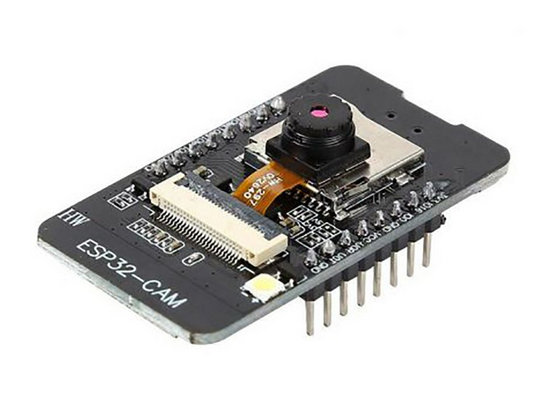
It uses an Espressif ESP32, which I’m very familiar/comfortable with, and is about $6. The camera sensor is 2MP, which is small for images, but fine for video.

There are a lot of timelapse projects out there using this board, but none of them really have the features I’m looking for. Espressif even has an official “webcam” codebase that others have packaged up into cool projects. But here are my requirements:

  • A web interface to control capture / timing parameters
  • Serving up images over the web interface to check that those parameters are good
  • Saving images to SD card
  • Nonvolatile storage of the parameters, along with the current snapshot number, in order to gracefully recover from power failure
  • SD card images available to download over the web interface
  • Over-the-air updating
  • Reasonably well-laid out codebase that’s easy to hack on

Essentially, I want to be able to plug this into a hard-to-reach closet and not have to ever physically touch it again. Lots of projects have a subset of these features, but nothing has hit it all, that I have seen.

One of the other ideas I had to improve upon the typical timelapse design was to get the ESP32 periodically grabbing the real-world time from NTP servers. It’s set to run every half an hour, which is probably too often to make a difference that overcome the latency from hitting the NTP server. Regardless, it should keep average timelapse interval perfect over a long period of time.

So I hacked something together. Originally I used PlatformIO with the Arduino framework, because it’s quicker to get a project off the ground than the official Espressif ESP-IDF. The branch is still there, but I abandoned it after running into issues with partitioning, OTA updating, and the additional PSRAM hardware all working together. The main branch uses the ESP-IDF now.

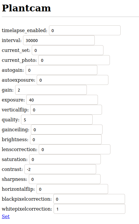
It’s essentially a webserver that controls the camera. You can open up a page and modify settings, including timelapse intervals:
 

You can also get existing parameters:
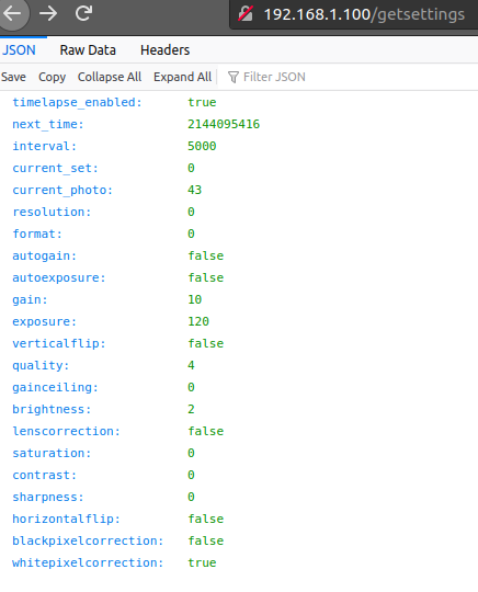
 

And snap takes a one-off photo to check your setup without touching anything. That made this super easy to tweak with one hand, while holding a laptop with the other.

When a sequence is done, it’s easiest to grab the SD card and plug it into a computer to copy over the files. For longer sequences, maybe to check progress, it is totally possible to grab the images over the web interface. Just slow.

To stitch together all the images, initially I used this command:

ffmpeg -r 30 -start_number 1 -i %06d.jpg -vcodec mpeg4 -vf "transpose=1" -y movie.mp4

That results in a pixelated and honestly pretty crummy output. It’s fast, though.

This got much better results:

ffmpeg -start_number 1 -r:v "480/1" -i %06d.jpg -pix_fmt yuv420p -c:v libx264 -preset slow -vf "transpose=1" -y -f mp4 movie.mp4

ffmpeg is a little inscrutable, so the parameters that require tweaking warrant an explanation. Order matters, too – Some of the parameters affect the input, some affect the output, depending on position.

-r:v is the input frame rate, relative to the base (25 FPS) framerate. So a 250 frame video with -r:v 25/1 would be 10 seconds, while setting it to -r:v 50/1 would result in a 5 second video.

The -vf transpose option rotates the video. The ESP32-Cam’s camera is mounted sideways, but that’s a minor irritation.

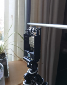
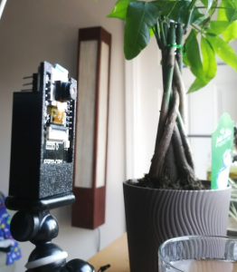
To mount the device, tripods are the obvious choice. I created a quick, minimalist enclosure that allows access to the GPIO pins, SD card, reset button, and fits a 1/4″-20 nut that is compatible with most tripods. A Gorillapod, in my case.


For the video posted at the top of the page, here is the setup:
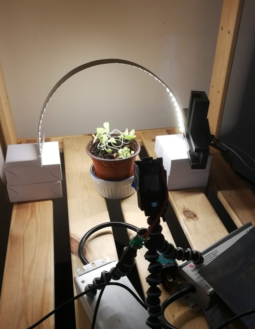
 

It was done with a picture taken every 40 seconds, 8 second exposure, low gain and brightness.

ffmpeg -start_number 1 -r:v "120/1" -i %06d.jpg -c:v libx264 -preset slow -vf "transpose=1" -y -t 00:00:08 -f mp4 movie.mp4


The -t option sets the end-time, there was a lot of “content plant” at the end that wasn’t moving much.

Future goals might include shoving the whole mess into a closet, along with timed control of the lights and a watering pump, and leaving it for a month.

Clearing out the backlog

A couple years ago, I started work on a timelapse camera module. I built one board, came up with some corrections, and designed a better version. Then it stagnated for quite a long time.

A few months ago I checked over the files again and sent them off to a fab shop.

After the new boards arrived, I couldn’t find a local source for some of the components I needed and it sat for a long time again.

A few days ago I found some components that would also (mostly) work, so I started the project up again. Let’s get ‘er done.


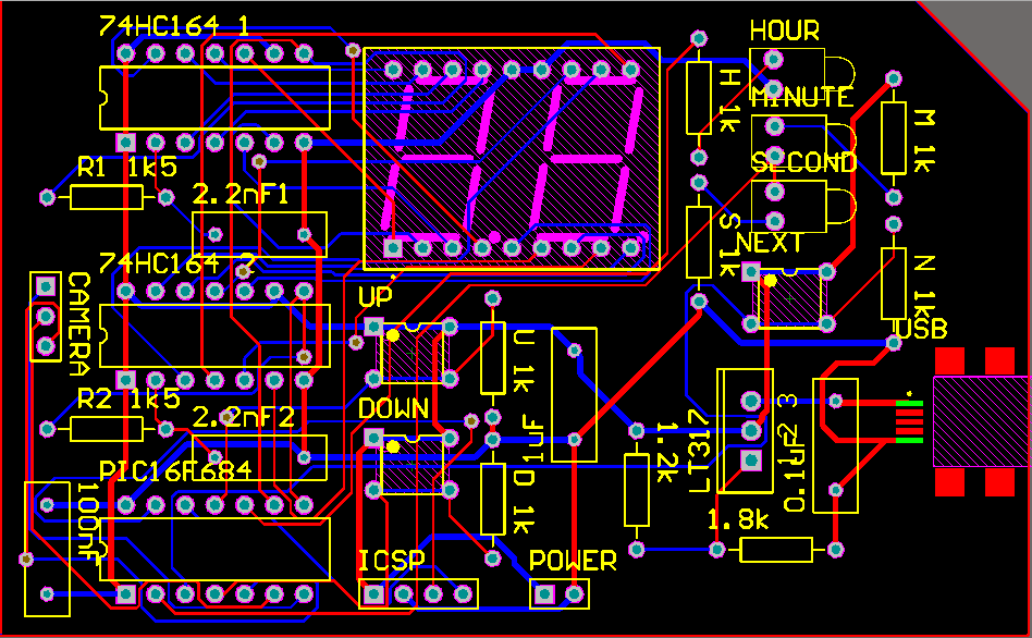
The goal of the project was to be able to hook into any 2000-era tiny resolution digital camera and take a picture at set intervals. It’s powered by USB, and regulated down to 3.3v that most cameras use. There’s a very simple 7-segment-display-based interface with which to control the timelapse interval.

It’s powered by a PIC microcontroller, and the display is driven by a couple 74HCT164 shift registers by TI. The “HCT” portion of that is key, because these are both wide-voltage range (to be able to run off 3.3v), and fast enough to clock 8 times without visible flicker.


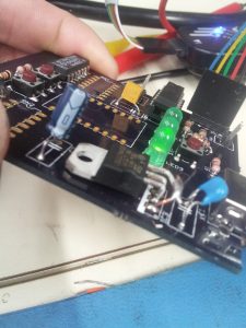
Here’s where I’m at right now:

I don’t have the 3.3v regulator that I designed for, but I found a different one that is adequate, with some bending of pins. None of my capacitors are the right footprint, and I don’t have the right resistor network package. All of these parts are pretty easily available off Newark/Element14, so I’ll have the appropriate parts for my second prototype.


Other than that, it looks pretty good. Keep in mind that I designed this version over a year and a half ago. I’m in a very different place now. Here’s what I would do now (or will do for a redesign):

  • I’ve mostly sworn off resistor network packages.
  • I realize I should have added a couple more decoupling caps.
  • I prefer to use SMD to DIP now.
  • With surface mount, I could also make this whole board much smaller.
  • USB-A male-male cables aren’t really common anymore, it would be much more convenient to use a microUSB port.
  • Driving the camera inputs would probably be safer with a transistor instead of directly from the PIC.
  • I need mounting holes.


I’ve rewritten the software. It stores timer values in EEprom and uses an interrupt to trigger the camera. At a later date, I’ll add in sleep settings for power saving, and control the camera on/off state for the same purpose.


For the interrupt, I want it triggered about every second. It triggers every time the 2-byte Timer1 register overflows. With the maximum prescaling dividing the clock (and register) to one second, I’d have to set the clock speed down to 1MHz. That slows down other parts of the program, enough to make my software-SPI-controlled display have visible flicker. That’s not cool.

To get the proper time, then, I need to count off a bunch of interrupts until I get to 1 second. I’ll calculate a good set of values for Timer1 to do the necessary.

Fosc / 4 = 1MHz

1MHz / 8 prescale = 125kHz

Period = 1 / 125kHz = 8ms

1s / 8ms = 125000 clocks

Say, 125000 / 2 = 62500 clocks

65536 clocks before overflow – 62500 = 3035 starting value (and decrement seconds every other interrupt)

After measuring against a stop watch for two and half minutes, it’s about 3 seconds too fast. That’s 3 / 150 seconds, or about 2%.

So change the starting value to 3035 * 1.02 = 3095.

I’m using the internal oscillator, which tends to be pretty inaccurate. That’s okay, I can tune it. A good way to do that is to take timelapse photos of a clock when I’ve put everything together. I’m curious how much it’ll drift after I calibrate it due to time or temperature. It’ll be an experiment.

Pictures of the build process to follow.


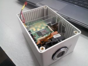
At first, I was lamenting not having proper mounting holes on my PCB. After examining the chassis I had lying around, though, this is perfect. The ribbed interior can hold slices of acrylic, and, properly cut to shape, they’ll sandwich both of the boards, the 7-seg display, and the lens assembly exactly where they need to be. No fasteners, and no unnecessary holes. Perfect.

Elapse

Shortly after I began building my clock, about a year ago, I got an insane job doing insane things for insane amounts of hours per week. Because I spend a lot of time on the road, I needed a more design-oriented project that I could bang out on my laptop for a long time without needing a soldering iron. So I pulled a new project from my bucket list.


Problem:

I want to play around with a time-lapse camera. Time-lapse mold, fungus, and plants growing look totally awesome, so I’ve decided that I want one. Most of the videos you can find on youtube or nature documentaries or wherever are done using a professional lighting rig, a DSLR, and an intervalometer. I don’t own any of those, and if I did, I wouldn’t want to leave my expensive camera in a spore-filled room for long periods of time, preventing me from using it for other things.


Solution:

Make a dedicated time-lapse camera on the cheap.


My progress so far:

Pretty much all of the materials have been gathered. An old digital camera has been sourced from Freecycle, the important stuff (lens assembly, control boards) fitted into a chassis. The schematic has been chicken-scratched into my notebook, and the PCB is ready to be etched. I’ve never done that before, so we’ll see how it goes. The PIC code is done, the design is laid out, I just need to build and debug everything.

Hopefully I’ll have some real progress soon.

The Mona Lisa

This is all you get, the circuit diagram is on one of my many many tattered notebooks in my workspace