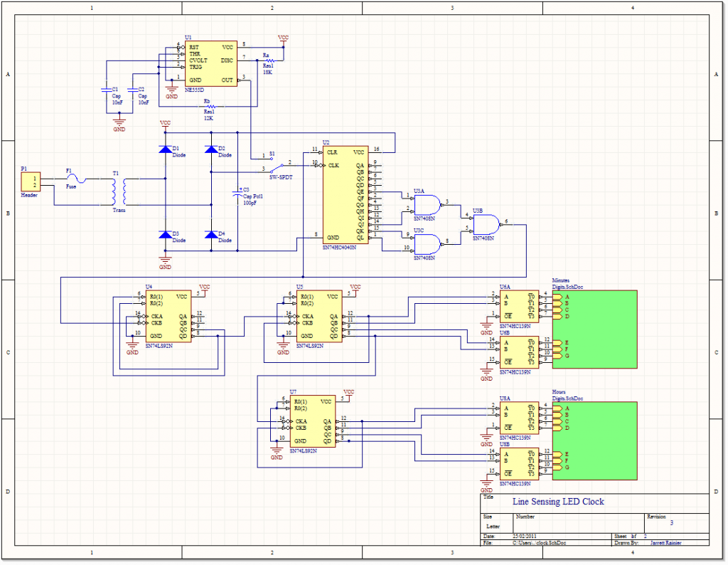
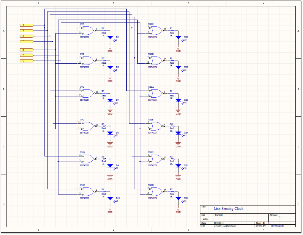
Getting the time.
Adhering to my “don’t buy anything” policy for this project, I’ll be using the 5V charger for my old Motorola Razr for power. I’ll have to open it up and find a stepped-down voltage that hasn’t been rectified yet. Then I can use divider chips that I have on hand to get the frequency I need.
Setting the time.
The “set time” switch toggles the clock input of the counter chip U2 from the 60Hz line voltage to the much higher frequency 555 circuit.
I’ll set the frequency to, say, 3600Hz and the capacitor to a common value of 10nF, then Rb = 12kΩ and Ra = 18kΩ.
Things that I could do better (but won’t):
- The switch isn’t debounced. This is bad. Every time you hit the switch, U2 will get clocked several times due to the switch contacts bouncing. The likelihood of this unexpectedly advancing the time is only three or four times in every 360.
- A much better way of setting the time would be to use pushbutton to cause a monostable 555 sending a pulse to an astable 555 long enough to clock U2 360 times, advancing the minute hand by one. And something similar for the hour hand, too.
- A potentiometer could be used instead of Ra or Rb, allowing the user to adjust the speed of the minute hand.


