I prefer to do most of my laser-cutting purely in 2D. The open-source vector software Inkscape totally rocks my socks off, and I can design things about three times faster using that than anything else.
When a design gets a little complicated, though, or it’s hard to see how everything fits together, it’s sometimes easier to model everything in 3D right from the start. So I built a linear actuator with SolidWorks.
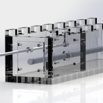
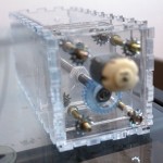
If you can’t see, it’s a DC motor that rotates a threaded rod, with that slider piece in the middle holding a captive nut and a rod. You drive the motor, the rod goes in (or out).
This was just a proof-of-concept to see how it all fit together. I wasn’t really happy with:
- The amount of material it used up
- The physical size
- Way too much friction in the system
- Possible strength issues in the rod
- No way to read or track the rod position.
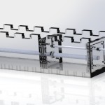
Solution: Mark II.
- Replace the DC motor with a stepper
- Triangular chassis for less material usage and size
- #10 threaded rod instead of 1/4″, also for size
- Add some bearings
- Triple up the actuator rod.
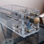
It’s very slow, but that’s simply a matter of choosing different motors and is acceptable for now.
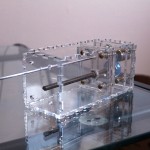
The bearings I had on hand are standard axial bearings; totally not suited to radial loads. That’s something I’ll have to come back to. I saw a method of laser-cutting the races to make custom thrust bearings recently, I’ll have to see if that’s appropriate for this application.
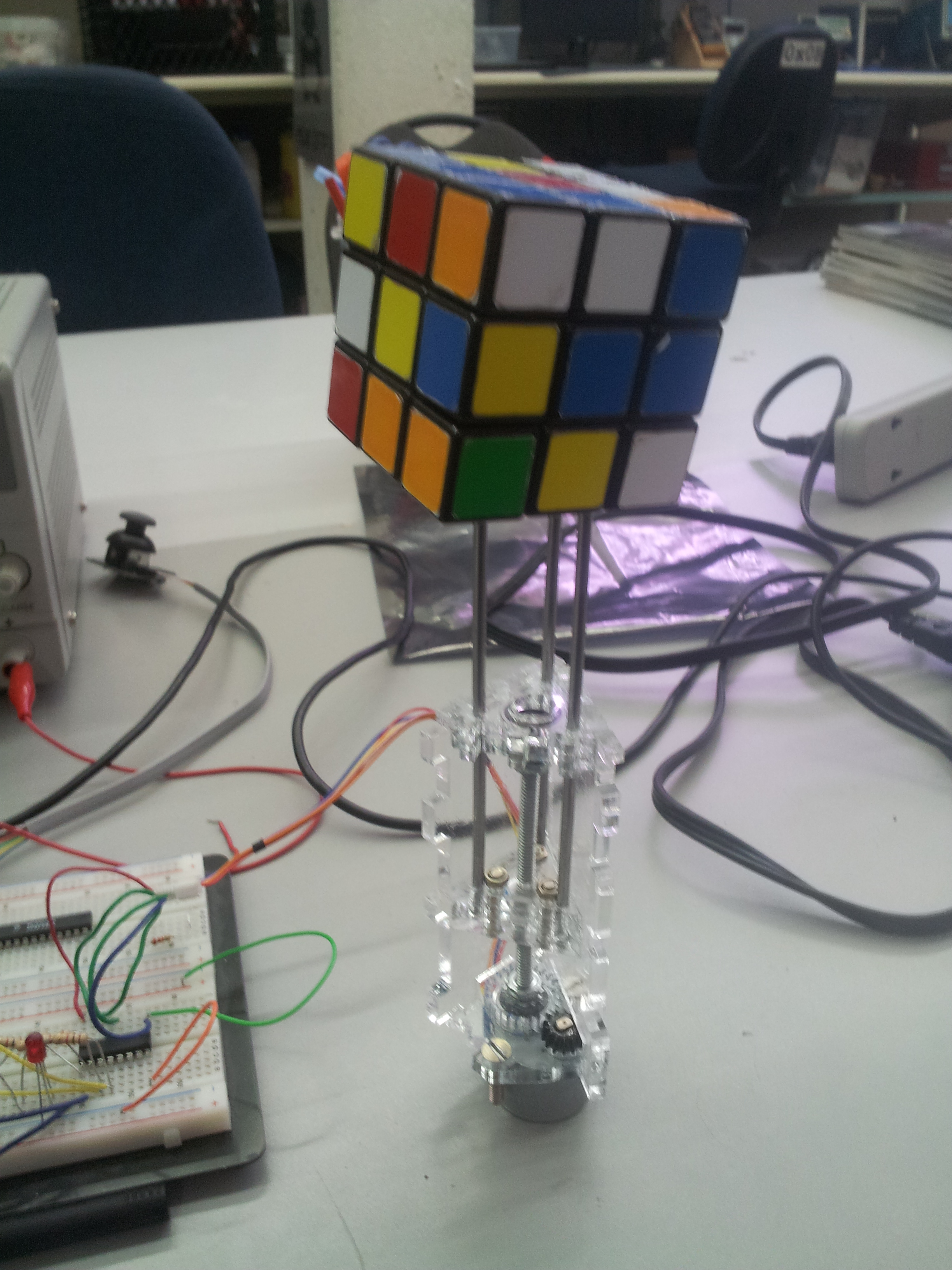
Terrible picture, will be replaced