I’ve been working on an ESP32 module.
Part of the problem I’ve been seeing with inexpensive IoT dev boards, is that the design around the power system hasn’t been very good. Here’s my attempt to fix that. This is a battery-ready module with a proper lithium battery charge circuit, lithium battery protection circuit, power supply, and antenna, all in a 1 inch by 1 inch package.
The goal is to have a tiny, inexpensive module that can immediately accept a battery and be deployed in the field, along with 30 of its mates.
The battery/power circuitry is surprisingly complex, which is why the built-to-a-price-point applications often don’t have the “proper” battery control, opting instead for “good enough”.
And when I say tiny, I really do mean tiny.
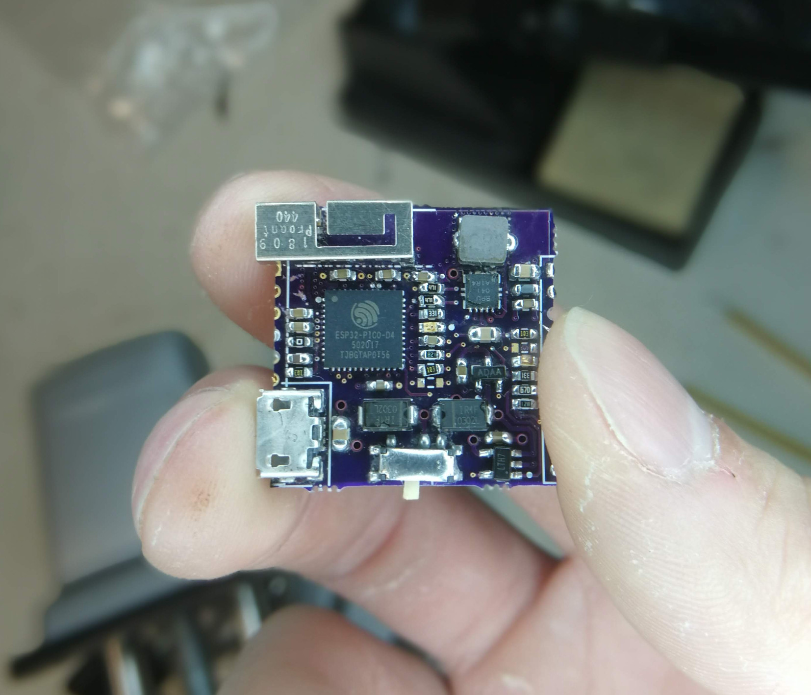
The main interface to the world (other that WiFi or Bluetooth) are castellated headers on the left and right side. Those grant access to input voltage, battery voltage, output voltage, TX/RX pins, bootmode selection, and a few GPIO. Because of them, this module can be soldered directly down to a larger host board if necessary, and can even provide regulated 3.3V output to it if given battery power.
What sets this apart in terms of battery handling are a few things:
- There is a buck-boost power supply to provide a constant 3.3V to the ESP32 through a battery’s entire range (3.0V-4.2V)
- There is a cut off for battery when it hits 3.0V, to prevent over discharging it
- When the module is plugged in (through castellations or through the USB connector), it will switch over to using that as a power source. It can be hot-swapped
- Also while plugged in, there is circuitry for constant-current/constant-voltage charging of the battery
- The battery will still charge while the device is switched off
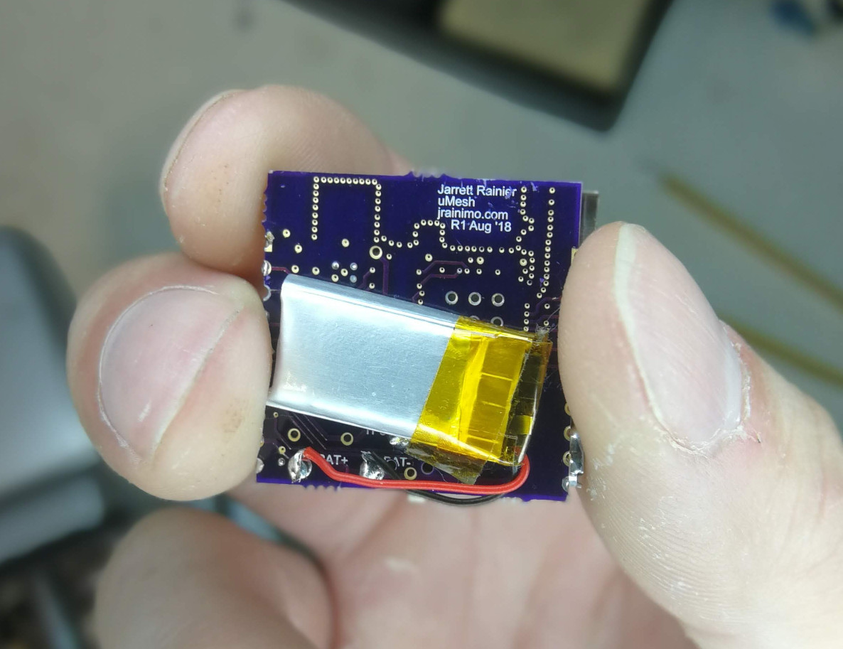
The battery just solders on to some pads on the back. Any size of single-cell will do, although the programmable charge speed relates to a resistor value that is soldered at manufacture time.
The USB port is for power/charging only, and has unconnected data pins. I also somewhat expect this microUSB port to shear off at some point, as they have kind of a history of doing that.
For the microcontroller, I’m using an ESP32-PICO-D4, driving a metal stamped antenna for 2.4GHz through a pi filter and 50 ohm impedance matched traces.
I haven’t really considered applications just yet, but it certainly does fill a niche for most IoT projects, given that a battery is usually necessary.
While waiting for shipping, and personal time to build it up by hand (mostly the latter though, Oshpark is awesome), I wrote an assembly and bring-up manual. It’s currently clocking in at 17 pages, but that includes a lot of reference. I’ve uploaded it as PDF here. That includes full schematics, part positioning information, net list, and BoM.
Here’s the Oshpark link to the project where it can be ordered (or gerbers downloaded too). It is a 4-layer board, and costs $10 for three.
Soon, I’ll write about programming it in an extremely sketchy way, programming it with the programming host board I designed, designing and tuning the antenna, and how to design it into a larger project.
Pingback: uMesh – A self-contained, battery operated ESP32 module – gStore
Pingback: uMesh – A self-contained, battery operated ESP32 module - Electronics-Lab
Pingback: uMesh ESP32 Module Offers a LiPo Battery Circuit for Deployed IoT Applications | iotosphere - Internet of Things
Pingback: uMesh – A self-contained, battery operated ESP32 module -Use Arduino for Projects
Pingback: uMesh - ATMega32 AVR