Archive for Jarrett

Laser Cut Spice Racks

I’m still transferring my SolidWorks knowledge into Fusion 360, and definitely getting the hang of it.


Previously, I was having troubles mating parts properly, which totally makes sense. The way Fusion 360 and SolidWorks handle these concepts are the largest difference in workflow so far.


Where SolidWorks requires each “part” to be one object, and all parts must be added to an “assembly” for positioning and mating, Fusion 360 allows all of these to happen in one file. When a part is created, however it is called a “body” and must be turned into a “component” before repositioning or aligning it with other component. I’m not sure the benefit of this, but hey, that’s how it works. After a body has been turned into components, the “joint” command is analogous to SolidWork’s “mates”. They’re a little bit more finicky, but they work.


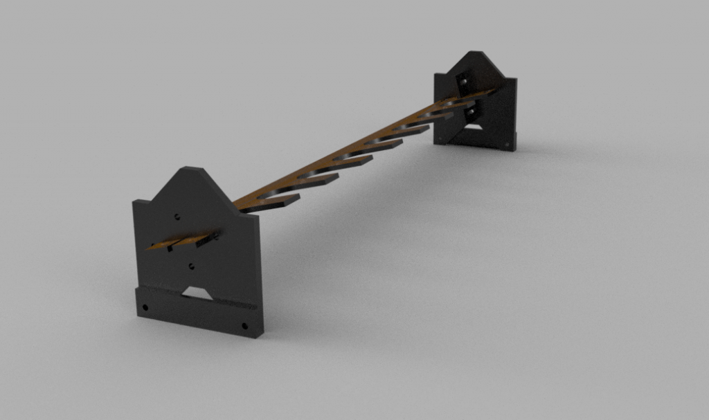
shelf v25


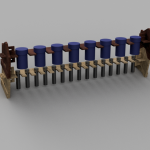
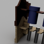
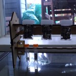
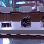
Here’s the latest experiment. Once again, this is almost entirely parametric. I had an idea to store all of my surface mount components in vials, and this is a pretty ideal way to stack them up. I realised about halfway through that, while designing a vial storage rack, it’s basically a spice rack.

One of the problems with this, is that over time I’ll be adding to it. Next time I need to laser cut some more, am I going to be able to find the same size of container? Am I going to be able to use the same size of material? What if I want a different sized rack to fit into a particular spot? Parametric!

There are a lot of variables in this one. Fortunately, most don’t have to be touched, usually.

In adapting these for different container size, the important variables are shelf_numVials and all of the vial_ parameters.


For the larger ones I got from the dollar store, they are:

vial_height = 48.75 – 11.5mm

vial_diameter = 27.5mm

vial_lidheight = 11.5mm

vial_lidDiameter = 31.25mm

These are unlikely to be available anywhere else.


The smaller ones from China are:

vial_height = 49 – 9mm

vial_diameter = 10.75mm

vial_lidheight = 9mm

vial_lidDiameter = 12.5mm

These are orange-lidded, 1.5mL plastic test tubes from AliExpress.


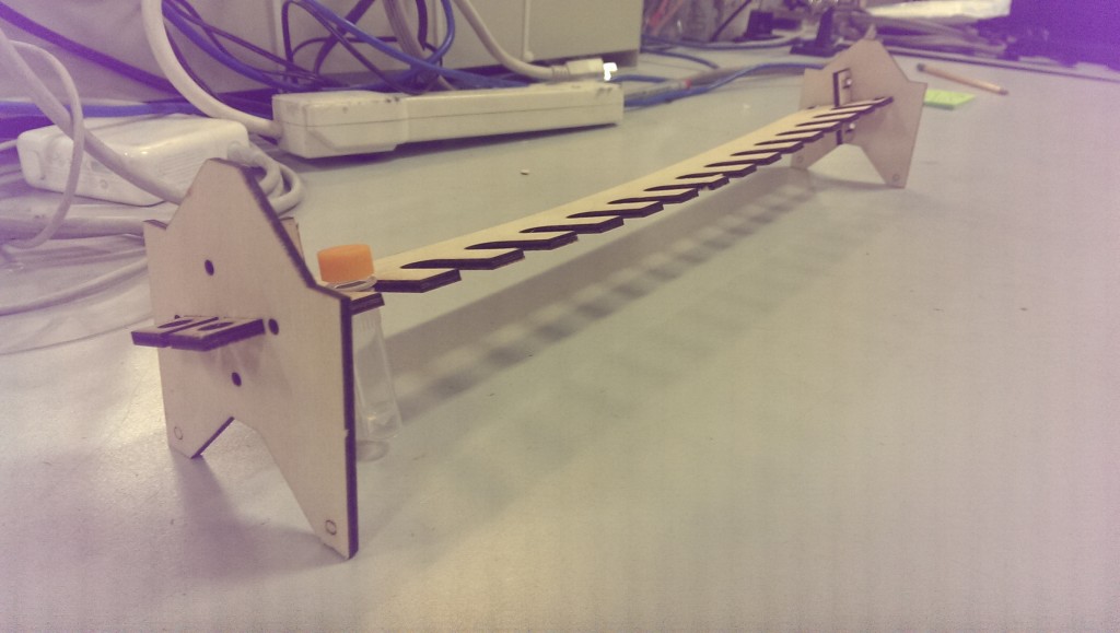
I’m now at revision 3 – The first one I cut sagged a little more than I would have liked, so I designed in a back piece at a right angle to straighten everything up.

Spice Rack R1


That worked, and stacking R2 on top of the first version pushes the ends out – effectively pulling it straight.


All of my files are available on GitHub here, or through Autodesk’s weird cloud platform.
Here’s an older version showing them stack:

http://a360.co/1X4LDGb


Here’s the latest version with all the bells and whistles:

http://a360.co/21Q52Bq

This is the one you want, if you’re planning on doing something similar.
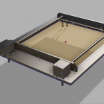
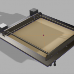
Reconfigurable CNC platform

I’ve got a big thing about building stuff in a modular way.


So I installed Fusion 360 yesterday, and I’m pretty impressed. Fusion 360 is a new SolidWorks competitor by Autodesk. Basically a $6k-8k CAD package, released free for hobbyists or businesses making less than $100,000 a year. That’s quite a hook.

Especially considering how good it is already. It’s not quite at par with SW, but the feel is very similar, and I can see it eventually being a strong contender. Plus, you know, free.


The parametric engine is also very good. I’ve been meaning to build a CoreXY platform for a long time. It’s an open source belt-driven CNC platform with balanced forces in the X and Y axis, an excellent build-area / platform-size ratio, and parts that are amenable to laser cutting. There isn’t a specific project it will go with, but you never know when you need to drop a CNC system into something. CNC everything!

The idea behind building it is that I’d like to be able to design and build a platform to conform to whatever my requirements for a specific project within about a day or so. There are a few major variables that could potentially change:

  • Motors
  • Belts / pulleys
  • Precision rod
  • Material thickness

I’ve already purchased belt and pulleys ($10 for the cheapest GT2 belt, $10 for matching pulleys), and ideally, I’d be able to use the rest of those common items that I have kicking around, or can scavenge easily.

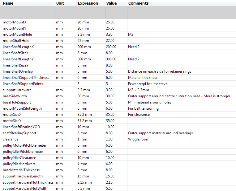
So I redesigned the CoreXY platform entirely using variables and formulae. Based on the waterjet cut CoreXY. Here’s a list of the variables that you need for a CNC, apparently:

CoreXY VariablesThat’ll change a little as I continue tweaking.

All other measurements are derived from those. Now when I need a new system, I take stock of the motors, sheet material, and so on, and enter the values into the window. A laser cutter file magically appears on the other end.

Here’s my project. It’s definitely subject to change. Accounting for laser cutter kerf is on the roadmap, and waterjet cutting would be good to design for, too, although I’m not super familiar with the constraints on that.


The files are located in the cloud right here.


One thing that I had problems with, is that Fusion 360 is not capable of reading parameters from subassemblies or parent assemblies. I had to copy the same set of variables to all of my parts, which is pretty annoying. Some internetting says that this feature will be implemented Real Soon Now(tm), as of 2014.


A good help for that was an add-in called ParameterIO. It doesn’t work out of the box, though, there is a bug because of the dimensionless quantities in linear patterns.

I had to edit line 219 of:
C:\Users\Jarrett\AppData\Roaming\Autodesk\ApplicationPlugins\ParameterIO.bundle\ContentsParameterIO.py

To say this:

unit = ' '
 try:
     unit = _param.unit
 except:
     unit = 'null'
 result = result + _param.name + "," + unit + "," + _param.expression + "," + _param.comment + "\n"
 

(Full file here for easier copying.)


That allows you to export all of the user parameters, and also the model parameters as a CSV file. The same bug causes problems when you try and import!

Fortunately you can delete the second half of the CSV file before importing, because the model parameters are a useless thing for unrelated parts.

An add-in to automagically inherent all parameters from parent assemblies would be awesome, and fairly straightforward, from the looks of things.

Maybe this feature already exists and I just haven’t found it, or maybe I will have to work on it when I’m done the X axis of this thing.

I don’t lamp well


That was a long “next month”. A recap is in order. This post chronicles the long descent into complete and utter apathy.


In September 2014, I made some sketches for a lamp I wanted to build. The intent was to use the glass plate from a desktop scanner as the light diffuser, and laser etch a fractal pattern onto it to create a frosted effect, instead of being optically clear.

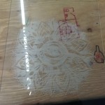
Here is a test piece I did, with a laser cutter and an image found off the internet.


The results were pretty fantastic. Fine details get lost, because it looks like the mode of operation is the laser heating up enough of the glass to chip off a small chunk before moving on. And so on, for the entire image. It creates great looking, even optical diffusion, though.


For another test, I decided to design and build a similar, but smaller lamp. Glass scanner beds are a limited supply. Using a glass tile I found at a craft store, I designed an arm to hold it onto a wall, a few centimetres away from a PCB containing some high power LEDs.


The initial model and 3D print is shown on my previous post.

Here is the final version, with some corrected measurements and better mounting point.

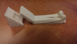
Lamp print


And the PCB arrived shortly after the last post.


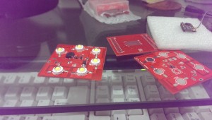
Lamp PCB

Oops!

That’s mistake number one. Everything was intended to be clean and white, but I guess I forgot to change the soldermask from the default DirtyPCBs red. It’s not the end of the world. This is a prototype of a prototype, after all.


The first board was populated, and then the lamp languished for a year and a half.


Recently, I found it buried in a locker and tried plugging it in for the first time. With no prior consultation to documentation, I tried it on a bench power supply, starting at 5v. Nothing happened, so I turned it up to 10. At 15v, the semiconductor on the board released some smoke and glowed red for a few minutes.

Nope!


Back to the docs, I read that I had used an adjustable 5v boost converter, so that solved that.

I soldered up another board (I had two spares of the IC), including the DC barrel jack this time, and plugged it in again. Turns out I had the wrong polarity!

No smoke, but some troubleshooting proved that I had definitely fried the chip.


This was pretty much the limit of how much I cared, so I did what anyone would do:

I jumped over the active parts of the circuit with a power resistor, and ran the LEDs directly from a 19v laptop power supply.


Job done!

Next time I’ll build in some more safety factor.

Additionally, looking at the lamp from the side is really really bright because of the bare 1W LEDs. I kinda planned for this and put some slots in the side of the base for some acrylic sheets, but I’m quite done with this design.

Snap-on Desktop Widgets

And now, for my next trick, I’m going to manufacture a million tiny monitor widgets to snap onto your big monitors to monitor your widgets.


Still with me?


This is a project with many parts, but I will only get in to one phase on this log.


I’m hooking up an ESP8266 WiFi module to an inexpensive TFT LCD. The idea is to have an internet-connected, smaller-than-credit-card sized screen that displays one thing, and one thing only.

Some use-cases could be the two-day weather forecast, a slideshow picture-frame, or a graph of the current price of Bitcoin. Things that don’t require more than a couple changes per second, and don’t warrant using up real estate on a main monitor when work needs to get done.

The system design is actually really simple. A mini-USB connector is feeding power to a 3.3v linear regulator, and data to a USB-UART bridge. The bridge is able to program the ESP8266 via USB to a host computer, but that is not required for general operation. A standard cellphone charger plugged into the USB connector for power is fine. The WiFi module connects to an Access Point periodically and grabs a static image from a website.

This image is then fed to the LCD. That’s it. That’s all it does. I’ve gotten the BoM cost down to around $8 each, so it’s reasonable to have a lot of them on a desk, displaying various bits of data.


The hardware files, including Gerbers, of revision 1 are here. There are also folders for the firmware, software, and test rig, but as of the time of writing, that is all very much a work in progress.

That link will soon be outdated, but I’ll tag the first revision as a “Release” in GitHub when I’ve got the different parts working.

As for next steps:

The LCD I’ve chosen is one of the cheapest ones I’ve found. It has a parallel data bus for communication, and I’ve used a 74HC595 serial-parallel chip to make it work with the ESP8266 module’s limited IO. I’m using an ESP-12E for reference, but trying to make it work with the original ESP-12 as a bonus.

Schematic

I think I can do some interesting things by replacing both the SIPO and the USB-UART bridge with a microcontroller. Things involving bootloaders, and things involving cross-monitor communication. Cool stuff.

Hysterical

After building my Piccolo and playing around, I really don’t like the software. It’s certainly simple and hackable and does a lot of what I need to do, but something about the Arduino/Processing pair don’t quite work for me.

Fortunately it’s just a bunch of servo motors, and I already have the PIC code in my toolbox.

Using my Arduino-form-factor PIC dev board and my Bus Pirate as a computer-UART bridge, I wrote in a simple protocol to communicate.

The “communication enable” pin will go high, and then two (might change to three) bytes get sent. The first is an “address” or command, and the second (or second two) bytes are a value/argument.

The 0 address is X axis, 1 is Y, and 2 is Z. The Z only uses binary 1 and 0 for arguments.

The z axi has two states: active and inactive. Inactive/up is the parked position, obviously. The active mode has a hysteresis loop attempting to control the position. The feedback is wired up to a window comparator, like so:

On the computer side, I’m controlling the Bus Pirate with a Python script that feeds it one scalar for a given axis at a time.

The speed at which the PIC executes the movement is controlled in the processor, to be tweaked. I will probably add that command in, when it becomes cumbersome.

As more commands become necessary, I’ll be adding more to the processor, I guess. Maybe eventually I’ll implement a rudimentary G-Code.


Now for the fun part:


Part of my original design goal was to have a 10ns response time. That’s very fast. Most of the old monolithic MOSFETs I’m using (because they’re cheap) have turn-on times in the tens of microseconds.

That totally blows my requirements out of the window, but there are still some optimizations to be made. By using analog circuitry, I can directly control certain parameters and speed them up, compared to hitting a microcontroller and being a slave to a clock source and interrupts getting in the way.

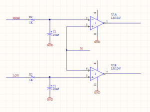
I’ve designed a window comparator. It looks like this:

Window Comparator

If the input goes above the “HIGH” voltage, then the top output turns on. If it goes below the “LOW” level, then the bottom output turns on. There will be two of these circuits. Feeding these outputs to some discrete logic, or something clever that I haven’t thought of yet, I can turn on or off transistors to the different power stages.

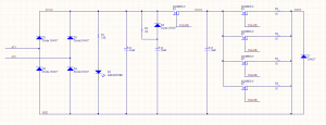
EDM Schematic V2

There are three power stages: Stage 1 (rectified input), stage 2(charge), and stage 3 (output).


The S2 MOSFETS can be ignored, just treat them as one. I should be able to parallel as many as I need, within reason, it doesn’t change (most of) the math.


The input of one window comparator is from VOUT, and the outputs are hooked up to the micro. If the HIGH output is on, then that means the MOSFET Q2 is on, but the EDM electrode has not made contact with the workpiece. Start (or continue) jogging the Z axis down.

If the LOW output is active, then we’ve gone down too low, start jogging up.

The other comparator’s input is at S2VCC. That controls the turn-on and turn-offs of the MOSFETS. If C3 is too low, then Q2 must be shut off and Q1 turned on to charge it up. When it is high, flip that. The idea is that Q1 and Q2 should never be on at the same time, providing a direct path to ground. The logic here will also involve halting the Z jogging, or making it jog up.


So there you go. With two different kinds of hysteresis going on at once, there will be some experimentation going on with how they work together. That leads me to one last trick:

You see the HIGH and LOW inputs on the comparator circuit? Those must be an analog voltage. That I’m going to set with a PWM out on the micro and the caps smoothing it out to an analog value. Varying the duty cycle of the PWM will allow me to vary the analog voltage.


Counting up my PWM outputs:

Two for each window comparator (4 total)

One for each axis (7 total)

One for the oil pump (8 total)


I haven’t discussed that last one yet, but stay tuned!


Altoids tin Pickit

Pickit is the officially supported programmer for Microchip’s PIC line of microcontrollers. The newest revision, Pickit 3, supports the latest and greatest micros, but does away with some fun stuff like in circuit debugging.

Fortunately, when Microchip dropped support of the Pickit 2, they open sourced the schematic so there are tons of clones out there that have all sorts of different features or design considerations.

There are through hole versions, dead-bug versions, versions built with components on hand, and versions built to original standards.


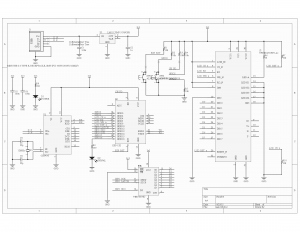
I’ll be using this Pickit 2 clone schematic:

http://diyfan.blogspot.ca/2013/06/original-pickit-2.html


I like this one because the official schematic has storage space for programming-on-the-go, which adds a lot of complexity. I have literally never used that functionality on mine, so I’d rather save the weight. All of these components are also easily sourced on the grey market. I’ve checked. They’re cheap.


Most clones are through-hole because they’re done on proto boards, but surface mount components are important here for keeping it low-profile.


So I’ve redone it in Altium. I’ve add programming headers for the PIC itself and broken out all the spare pins, but otherwise kept it pretty close to the original schematic.

I’ve also decided to fit it in the gold standard of hacky enclosure styles: The Altoids tin.

It’s kind of surprising that I haven’t seen this done before.

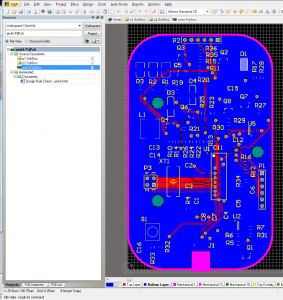
Using the Altoids tin dimensions provided by Adafruit, I’ve designed this PCB. The tin will require some cut-outs, but it looks pretty simple.

Here’s a teaser:

9


It’s two layers for cost, all components are on one side, and there are fiducial marks for a pick-n-place machine. Basically, I’m trying to make this manufacturable. I have no intention of doing so, but I did it because I could.

As usual for most of my projects lately, all files (including Gerbers) are here.

Note: The positive rail for the op amp is not connected to the VCC net. Whoops! Blue wire or respin required, if I ever come back to this.

Using Altium for a DirtyPCBs order

This is a pretty rare combo: using a premium PCB package with the budget board house.


Kinda funny.


Generally these small run PCB houses provide DRU and CAM files for EAGLE design rule checking and Gerber outputs, respectively. Because I’m using Altium, I had to make it up as I went along.


It gets much easier when you understand what Gerber files are. While we’re all used to standard, unified output formats that contain all of the data we need, Gerbers are very much still a holdover from manufacturing in the 80s.


When you export these, a whole bunch of files get generated. This is intimidating, but don’t panic! They all have different extensions like GBO, GTL, etc. These are all the same type of file.

As I’ve said, while you’re used to unique file extensions being different formats, these are a holdover from 80s manufacturing and the PCB industry still hasn’t caught up. That means that by changing file extensions, you can play around with different layers doing different things.


So here’s how you generate the appropriate Gerbers. I used a mostly the default rules for this, I’m not pushing the limits. Maybe next time I’ll generate the proper rule sets.

Read and understand these directions before you start. They require some forethought.


Start out with your finished PCB.

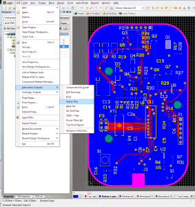
Capture


Do the thing.

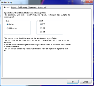
1


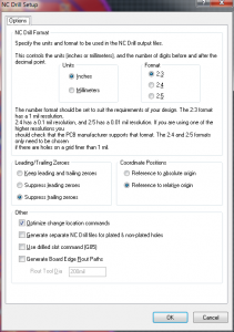
The resolution options matter here. There’s no way Dirty PCBs can handle the higher res, so turn it down a notch.

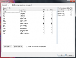
2


In the next tab, this is where you’ll have to do some thinking. Every project is slightly different. So for this one, I want the top overlay (silkscreen), top solder (gaps in solder mask for your pads), and top layer (copper). Same thing for bottom.

You also need a board outline. Older versions of Altium don’t have a dedicated “outline” layer, although I believe newer ones do.

So what I did was change the board outlines to Mechanical 1, and now I’m exporting that.

A couple more notes:

If I wanted to create a solder paste stencil, I would also export the Paste layers.

If you want through-hole slots, you will need an additional layer. This includes slots that allow you to panelize. Export them on another mechanical layer, and I’ll talk about it a little later. I’ve done this before, DirtyPCBs does a great job of this.

All of the other tabs in this dialog are kept at default values. Don’t mirror the bottom layers as shown. I did that and it was Wrong.

3

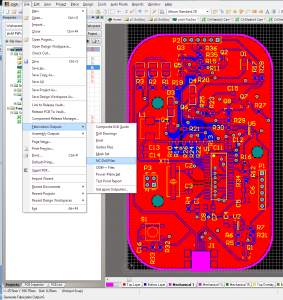
I lied a little bit above. Of the exported files, there is one that is not like the others. The drill file (.TXT in this case) requires it’s own export.

4

Do the resolution thing again, and everything else is default.

5

Okay! Now we’ve got all the files we need, let’s make sure they’re in the order they need. Here’s the key on the DirtyPCBs website.

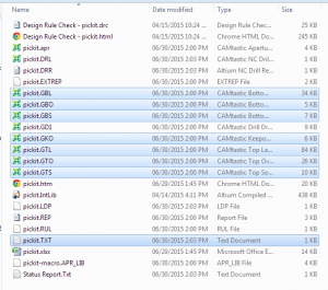
As you can see, it’s super similar to what we have. The top 6 are exactly what we exported, and the drill TXT, too. The outline is the only thing that’s not quite right.

6

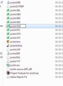
We exported it this time as mechanical layer 1. Easy fix, just rename the GM1 file to GKO. If you’re doing internal slots or self panelizing, you’ll also have exported another mechanical layer. Say, GM2 or GM15 or anything you like. Rename this to GML and include it with the others.

7

And there you go! Zip up all of these files, and they should turn out alright. GD1 is the Gerber drill file that this board house doesn’t use, just ignore it.

8

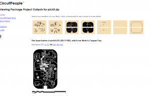
An important step: Check your files.

CircuitPeople is an excellent and simple online Gerber viewer. Look at all your layers and make sure nothing is terrible.


9


And you’re done! Send it off and enjoy your boards.

If something screws up in the order, I’d like to hear about it, but I take no credit. These steps have always worked for me, but this particular company probably won’t tell you if anything is wrong with the files. They’ll just manufacture it and send it on.


CNC Day

Aw yeah, CNC day.

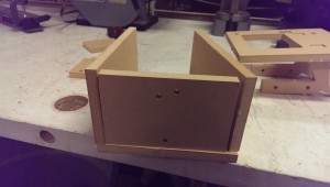
CNCed Tank

Pretty simple parts, I guess it wasn’t strictly necessary to use a CNC, but hey, it was there.


Here it is coming together.

Tank Test Fit


A spaceship!

CNC Spaceship


~~~~

Brief interlude

~~~~~~


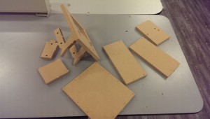
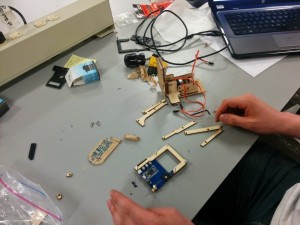
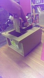
Laser cut Piccolo parts.


Piccolo Assembly


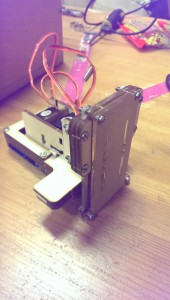
And the rest of it.

Piccolo Assembled

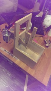
Rough-ish final box.

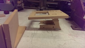
Small EDM Tank

And it flips up!

EDM Tank Up


So the next step is to figure out a way to mount the Piccolo on top of the box as shown. There’s a little bit of MDF I need to cut away to make it fit better, too.


After that, I need to modify the Arduino sketch (ugh) to jog the Z-axis up and down to keep the electrode in the conductive region.

WPA2 HMAC SHA1 PMK FPGA VHDL

Hell yeah, acronyms.

Restartin’ dis.

I’ve got the old working SHA1 encryption algorithm going. It’s up on GitHub, here. I was waffling between parallel and serial loads and outputs. SHA1 takes a 512 bit input and outputs 160 bits, and no FPGA that I have access to will have that many pins.

Here’s a fallacy I got stuck on for a while:

If I use completely parallel I/O, it’s faster. Therefore, I should try to use as much parallel communication as possible to maximise speeds.


The truth is, though, that most modern high-speed circuits use serial data. When you’re clocking at very high frequencies, propagation errors become very difficult to mitigate. With many data lines, you have no way of knowing when exactly data arrives at the lines. It’s better, easier, more reliable to just send one bit at a time and pump them through really fast. That’s a core principle of pipelining; you don’t even need to wait for a signal to reach its destination before you’re sending the next one.


With this project, I don’t think I can go faster than 100MHz with the FPGAs I have. That’s right on the edge of where efficient pipelining starts to matter, so I’ll be experimenting with a mix of serial and parallel interfaces to see how far I can stretch it.


Right now at this moment, though, I want to get the computationally-intensive parts of the WPA2 protocol offloaded to the FPGA. I won’t worry about speed juuust yet.


Here’s how WPA2 works, from a security analysis perspective:


Some definitions


  • Access Point (AP) – Usually the router, in these systems
  • SSID – AP name. This is the router name that you connect to
  • Master Key (MK) – AP password. This is the key we ultimately want to find
  • Pairwise Master Key (PMK) – This is the cryptographically hard part of the whole transaction. It’s derived from the MK and SSID
  • Pairwise Transient Key (PTK) – The cleartext portion of the authentication to verify the correct PMK
  • PBKDF2 (wiki, RFC) – Password-Based Key Derivation Function 2 – A cryptographic function, used like PBKDF2(PRF, Password, Salt, c, dkLen) where PRF is any given hash function, c is the quantity of iterations, and dkLen is the output length
  • HMAC (RFC) – Hash-based message authentication code – Intermediate function applied to the SHA1 hash
  • SHA1 (RFC) – Standard hashing function. Uses a one-way algorithm to generate non-reversible output


The AP has the password, from which it can derive the Pairwise Master Key (PMK). To verify that both sides of the transaction have this, a PTK is generated using the PMK and nonces (randomly generated, one-time-use numbers).

This PTK is transmitted over cleartext, and is part of the 4-way handshake.


So, in short, if you combine the proper PMK with the proper PTK, the whole conversation breaks wide open and you can associate with the AP.

If you’re watching the WPA traffic, then you can easily capture the 4-way handshake and therefore the PTK.


That means that, for my purposes anyway, the PMK is the important unknown variable, and the computationally hard part. Here‘s how you calculate it, from top to bottom:

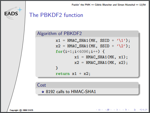
PBKDF2:

x1 = HMAC_SHA1(MK, SSID + "1");
x2 = HMAC_SHA1(MK, SSID + "2");
f1 = x1
f2 = x2
for(i = 1; i < 4096; i++) {
    x1 = HMAC_SHA1(MK, x1);
    x2 = HMAC_SHA1(MK, x2);
    f1 ^= x1
    f2 ^= x2
}
return f1 + f2;


HMAC:

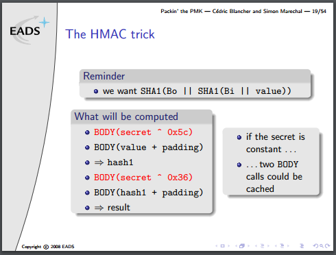
This is more complicated. Given HMAC(secret, value)

  •  Initialise two 64-byte variables, Bi and Bo with secret, padded with zeros on the end
  • XOR each of byte of Bi with 0x36, and XOR each of byte of Bo with 0x5C
  • Append value to Bi
  • Append SHA1(Bi) (in Ascii!) to Bo
  • Return SHA1(Bo)

In short:

HMAC_SHA1(s, v) = SHA1((s ⊕ 0x5c)||SHA1((s ⊕ 0x36)||v))


And finally, with the SHA1 function, I have covered it in previous posts. This portion is already done.

Imbles of Gimbals

I got handed a box of old gimbals from a movie set! I love gimbals!


Most of them are very slightly broken in very repairable ways.


I left, like, 5 for other people to fight over, and grabbed two for myself. One of them was in great shape, the other had some loose set screws and was missing an encoder. Fortunately the bin had some spare encoders!


Anyway. I stashed the good one, and focused on the brokenish one. Fixed it up, and started wiring up some drivers.


Here’s what the gimbals are like:

On the horizontal axis, there’s a DC motor with a gear meshing with the base. On the other side of the base gear, there’s another one connected to an optical encoder. There is also a photo-interrupter at one point along the rotation for calibration, I guess.

So the base can rotate freely in either direction indefinitely.


There is a slip ring that passes some wiring up to the vertical assembly. A similar system is in place for that motor, with an encoder tracking absolute position, but this one only has about 45 degrees of travel. There is a limit switch at either end, and a bunch of spare lines to be used for a camera or whatever.


This system is extremely easy to reverse engineer. All of the cables are out in the open, only disappearing into a slipring, where the maintain colour code.


So I starting breadboarding a motor driver. The brain is an old PIC that was in a bin somewhere, and I tried to find some driving transistors that would work. I burned a couple, and then took stock of what components I had on hand.
There was really no transistors around that fit the bill. I measured these DC motors to run at a good speed at about 8.5v and 500mA,so the power requirements are not low, when you’re trying to use 3906 BJTs or whatever.

Breadboard H-Bridge


That day ended there. I thought about the problem for a few days, then I came back and grabbed a 200w amplifier from the recycling bin and pulled it apart.


300W Amp Outside300W Amp Inside


Inside it were 4 sets of 2SA1908 and 2SC5100 complementary BJTs. Perfect. Wired them up like so, and I have a gimbal driver.

Gimbal breadboard schematic

Now I need to incorporate all of the sensors.