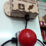
At a place that I hang out on very rare occasions, there’s a big red button.
When somebody holds it, it starts up an air raid siren that can get really loud. Unfortunately, it spins up very slowly, so people let off as soon as they figure out what the button does. That results in one tiny little blip of the siren, barely enough to bother anyone. That’s no good at all!
So for this build, I didn’t want to spend very long at it, and attempted to do everything very roughly and as quickly as possible. I found all of the appropriate components kicking around, and designed around those.
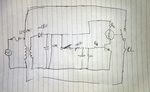
Here’s what I came up with:
I found a transformer with outputs that measure at about 12VAC. 10:1 winding ratio, I guess. After rectification and smoothing, it’s a little over 18VDC. On the right side, I used an ALA2F12, a 12V relay. The transistor is a 2N3904, just a very generic NPN BJT because this application doesn’t require anything special.
The original button was just the AC line voltage to the fuse, then through the switch to the load, very very basic.
Okay. Starting from the left:
- Transformer outputs at 12 volts or so,
- through the half-wave rectifier diode (1N4007 I think) – results in 12 * root 2, about 18V,
- big filtering capacitor (200v, 820uF),
- 1MΩ bleeder resistor so the system doesn’t hold charge indefinitely,
- original switch (connected to the big red button),
- 100Ω resistor(to prevent sparks)
- into timing cap (160v, 220uF) – charges to full very quickly,
- another bleeder resistor,
- Rb controlling current going into the transistor’s base (more on this later),
- BJT base.
- At the top: resistor controlling going into the relay coil,
- relay coil,
- BJT collector going to ground.
Because I’m abusing a 12V relay by driving it with 18V, I had to compensate for that a little. According to the data sheet, the coil is nominally 272Ω, taking 43mA of current. Ignoring the transistor’s collector-emitter voltage (probably ~0.2V): 18v / 43mA – 272Ω = 146Ω. So I tossed a 150Ω resistor in series with the coil, and it seems to work.
For the base of the transistor, this resistor (along with the capacitor) is what controls the active time of the system. It also controls the maximum current that can conduct through the collector-emitter junction of the 3604 Typically the gain of those are in the 70-100 range, so current going into the base should be Ib = 43mA/100 = 0.43mA. Base-emitter junction is around 0.7v, so the base resistor can be figured out by 18v – 0.7v / Ib when the base cap is fully charged. Overdrive Ib to 1mA to ensure max-on, so I used 18kΩ.
I tested everything to check timing issues, overheating, etc., and it works well. The relay gets latched for about 7 seconds, which is perfect. If I cared about being more precise with that, or wanted to change the timing values, it’s pretty simple to treat that portion as an RC circuit and tweak the resistor or capacitor values.
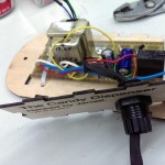
So I built it
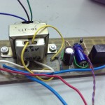
- Protoboard
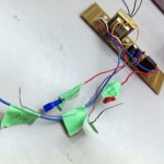
- Always label your wires.
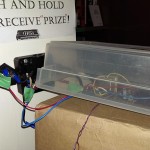
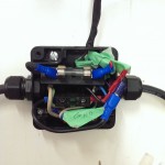
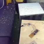
- Test box. You know, in case everything explodes.
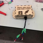
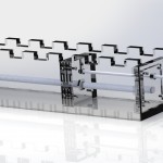
- Laser cut enclosure
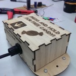
- All assembled!
- You can see the additional bolts I put in on the sides as standoffs. I designed the enclosure for one material, but I ended up using some much thinner scrap wood, so the box tabs stick out the back a little.
- Bolt it to the wall and hook everything up.
- The inside is getting a little tight…
- …But it fits.
- This version where I miscalculated the voltage is why I used a box for testing later.
Perfect! Start to finish, took about seven hours. Not including the abortive first attempt last week.
So before, when newcomers pressed the button, there was only a very short blip of the air raid siren. Now, the thing latched for a good seven seconds. And it gets very loud in that time.


