Archive for Jarrett

Pie-faced

There’s a new tool on the block, you might have heard of it. They call it a Raspberry Pi, and it’s neither infinite, nor raspberry-flavoured (I checked).

It’s a System on a Chip, or a tiny computer.

A big part of its selling point was that it was $25. This kinda got shifted up to “yeah, $25, but $35 for the really useful one, and then with shipping you’re probably not going to see one for less than about $45.”

So the economy aspect got lost a little bit. People started selling $20 cases, and $150 screens, and I think it’s all a little ridiculous. I’m not using it to replace my desktop computer here.

The beauty of an inexpensive and highly portable computer is that you can give it one task, set it, forget about it, and just go buy another one when you want to play with the platform again. You don’t need a large screen for that, usually.


With all of that in mind, I set about looking for the cheapest LCD I could find. I ended up with a replacement screen for a Nokia N77 cellphone. It costed $4.75. A little more research, and I even found someone who was driving them with an Arduino, and that’s most of the battle. The only problem is that it uses a hard-to-find proprietary connector. So that sat on the back-burner for a while.


Recently, an eminent change-of-address has spurred on a new project. And, suddenly, I need a small LCD again. After doing some re-evaluation, I’ve changed tack somewhat.

I’ve decided to go with a Nintendo DS Lite screen, and here’s why:

  1. You can get a digitizer to add touchscreen capabilities.
  2. It’s only a modest price bump. About $8 for the screen, and $1.50 for the touchscreen.
  3. They are far, far easier to consistently be able to source from eBay or any number of repair shops.

So I just pulled the trigger on that. While waiting for my shipment to arrive, I poked around for what other people have done with them.

Plenty of people have gotten the touchscreen to work with Arduino, PIC, and Windows. From what I understand, it’s just a couple of potentiometers.

No one really has any information about the LCDs, though, which is strange. Eventually I found a datasheet (via this guy) and an RPi framebuffer driver project. The DS screen isn’t on there, but the datasheet looks pretty straightforward.

I guess I’ll find out when it gets here.

Final pictures

Software

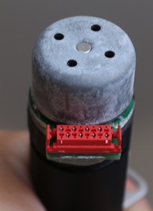
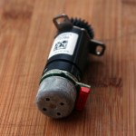
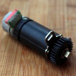
I’ve opened up two sacrificial motors, and they definitely seem to have some sort of on-board Hall effect sensors. I haven’t looked for the pinout yet, but chips were all labelled 1036 for one of the motors, and J588m for the other one. Google turns up nothing about these (that I can find).

The motor connector has eight pins, three of which are used up by the motor windings A, B, and C. That means two of the remaining pins are probably VCC and GND. The last three pins must be the Hall sensor outputs.

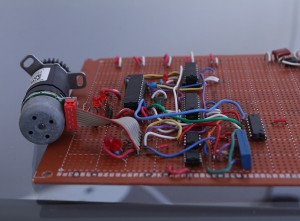
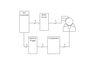
Currently, I’ve only got the motor running in open loop. That results in a working, but pretty crappy rotation. When I have some time, I’ll grab the feedback, and close the motor loop. Here’s the PIC code I have right now:


#include <htc.h>

//Int osc, wdt, mclr disabled, bor, fscm
__CONFIG(0x3BD4);

#ifndef _XTAL_FREQ
 #define _XTAL_FREQ 4000000
#endif

//Pres butan
#define PITCHFW    RA4
#define PITCHRV    RA3

#define YAWFW    RA2
#define YAWRV    RA5
//Outputs

//Motor variables (RC0, RC1, ETC)
#define PITCHA    0
#define PITCHB    1
#define PITCHC    2

#define FLOATA    3
#define FLOATB    4
#define FLOATC    5

//String constants
#define PITCHMOTOR    1
#define YAWMOTOR    0

//AC', AB', B'C, A'C, A'B, BC'
#define FORWARD        0
//BC', A'B, A'C, B'C, AB', AC'
#define REVERSE        1

unsigned char iPortCValue, iPitchStep, iYawStep;

void set_bit(unsigned char iAddress, unsigned char bBit) {
    iPortCValue |= (1<<bBit);
    PORTC = iPortCValue;
}    

void clear_bit(unsigned char iAddress, unsigned char bBit) {
    iPortCValue &= ~(1<<bBit);
    PORTC = iPortCValue;
}    

void delay_motor(void) {
    unsigned char i, e;
    for (e = 0; e < 6; e++) {
        for(i = 0; i < 170; i++) {
            asm (" nop ");
            //__delay_ms(1);
        }
            CLRWDT();
    }
}

void move(unsigned char iDirection) {

    delay_motor();

    //AC', AB', B'C, A'C, A'B, BC'
    switch (iPitchStep % 6) {
        case 0:        //AC'    AB'C'    
            PORTC = 0x29;
            break;
        case 1:        //AB'    AB'C    
            PORTC = 0x19;
            break;
        case 2:        //B'C    A'B'C    
            PORTC = 0x34;
            break;
        case 3:        //A'C    A'BC    
            PORTC = 0x2C;
            break;
        case 4:        //A'B    A'BC'    
            PORTC = 0x1A;
            break;
        case 5:        //BC'    ABC'    
            PORTC = 0x02;
            break;

    }
    if(iDirection == 1) {
        iPitchStep++;
    } else {
        iPitchStep--;
    }        
}    

void main(void){
    OSCCON = 0xF1;    //Internal osc
    TRISC = 0x00;    //Port C Tris output
    TRISA = 0xFF;    //Port A Tris input    
    iPortCValue = 0;
    iPitchStep = 0;
    iYawStep = 0;
    int i = 0;

    while(1){

        //if(RA2 == 1) {

            for (i = 0; i < 36; i++) {
                if(RA5 == 1) {
                    move(1);
                } else if (RA4 == 1) {
                    move(0);
                }
            }
            for (i = 0; i < 200; i++) {
                delay_motor();    
            }
        //}            

    }
}

Problem identification. The doldrums.

At this stage in the game, this project is on a clear path to completion, with no major revisions in sight. What I’d like to do is identify some issues that have made themselves apparent during the build and tweaking processes. Some are things that I would fix in the version 2, if one were to exist. Some I need to fix right now.

This also marks the end of the “let’s build something cool!” phase and into the “ugh. WHY isn’t this working?” phase. It’s a lot harder to stay interested in finishing, but I’m going to power through.

Here’s where I’m at:

  1. Limited rotation: any rotational movement that goes too far would tangle up cables that are driving the pitch gear motor. Everything in this system is designed to be battery-powered, so the obvious solution would be to mount the yaw motor on the rotating platform. That could mesh with an inside gear that’s been fixed to the base.
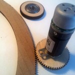
  2. Non-prime gears: this is one of the topics that have come up while doing ongoing research for what constitutes a “good” mechanical design. Generally, teeth shouldn’t continually mesh with exactly the same tooth and the opposing gear. That’s a good way to cause excess wear through dirt or inconsistancies in the the teeth hitting the same spot every time. To make sure that doesn’t happen, you want the gears to be co-prime. Right now, my two gear sizes have 55 teeth, and 280 teeth. That’s no good. Fortunately, 281 is prime, so that neatly solves that problem. The pitch gear doesn’t ever rotate all the way through, so that doesn’t fix the issue for those mates, but there’s nothing I can do about it, so why worry?
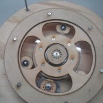
  3. Catching: the top gear(I’ve been calling it the pitch gear) catches up between the two gears providing support. When it gets caught, the gear likes to try and shove the rear support struts up and out of the base. This is the only problem(so far) that I haven’t foreseen. Fortunately, I was able to move that top support gear a little closer to the bottom portion using some holes that already existed. Anything less than 90 degrees seems to do the trick.
  4. Squeezed bearings: I used some flat washers on either sides of the bearings, but that still caused too much friction for them to rotate properly. I need to find some smaller nylon washers, or maybe flanged bearings.
  5. Wobbly base: the lower gear(I’ve been calling it the yaw gear) is mostly just sitting on a huge bolt that I had kicking around. I was hoping it would work, but no dice. It doesn’t quite. The gear wobbles around in relation to the base just enough to lose contact with the motor gear. When I can get some more laser cutting in, I’ll build another base with an additional cage around the bolt to provide more support.

Relapse (Build)

Putting it all together.


The materials I used are a little more than the final product requires, some material was used up in mistakes or scrapped in newer revisions, but here is what I started with:

  • 2′ x 3′ 3/8″ acrylic ($20)
  • 6″ x 6″ 1/8″ acrylic ($10)
  • 4x 3/8 bolts
  • 4x 3/8 lock washers
  • 8x 3/8 flat washers
  • 4x 3/8 nuts
  • 1x #6 machine screw
  • 1x #6 lock washer
  • 2x #6 nuts
  • 1x 5/8 bolt
  • 3x 5/8 nuts
  • 1x 5/8 lock washer (about $4 for all)
  • 1 cheap tripod for the head (can be replaced with 10mm bolts or threaded rod) ($3)
  • 2x bearings (26mm OD, 10mm ID, 8mm width) ($6)
  • 2x BLDC motors (I got these for free)

Relapse (Design)

In the time since I designed my timelapse camera gimbal, I’ve laid everything out for laser cutting, researched companies that offer cutting services, and very carefully decided not to send it out. As an initial draft, I wasn’t ready to spend $150 on a process that I’ve never used before.


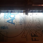
Fortunately, the excellent Laser Cutter Cafe recently started up on a temporary basis. The deal is, you can come in, take a brief training course, and rent time on a laser cutter. Compare to online services, this is relatively inexpensive, and you can cut smaller test pieces and see the results immediately. For rapid prototyping, this is a valuable learning tool.

At the beginning, I was finding that many of my designs had fairly glaring errors that weren’t apparent until I was holding a physical copy. Throughout the process though, I was constantly tweaking and updating the design, and now I’ve got an excellent handle on what works and how everything will fit together.

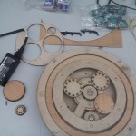
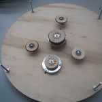
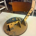
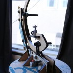
The tweaking process involved adding, removing, and moving pieces around to fit better. Initially, everything was going to be glued together, but with a combination of finger joints and mortises, most of the individual components slot together and can almost friction fit. Naturally, glue will still be used, but the assembly of the final product is nearly idiot-proof now.


If I were to print this again, I’d arrange the shapes closer, merging the the coincident lines to save on laser-time, but that wasn’t a priority while printing up the prototype.


Lightbox, State of my custom PCBs

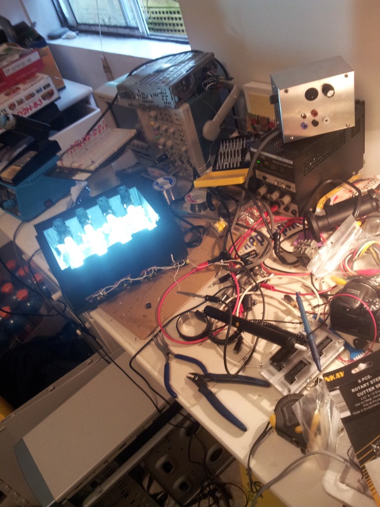
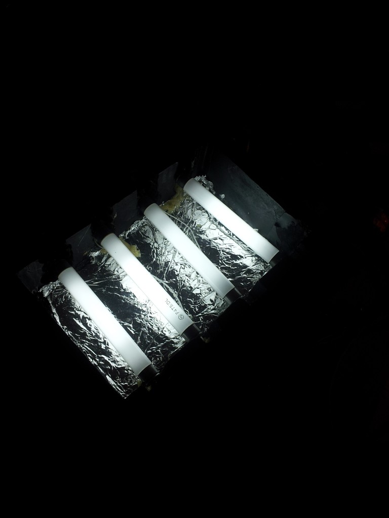
I should mention that sometime last year, I built a UV exposure box for manufacturing PCBs. It’s pretty rough, but I built it over the course of an evening to do one job, and it does it quite well. Or at least, I think it worked quite well.


20120512_184237


The idea of being able to conceive of an idea, draw a schematic and PCB, and create a physical copy of the device in a single day is extremely attractive. The problem is that the exact method is not an exact science.

Sure, there are a set series of steps that must be taken – Design a PCB, print it out on a transparency and use it as a mask for a photosensitive coating on some copper-clad, set the coating, then etch off whatever wasn’t masked off.

But every setup is different. People on the internet are using a different brand of UV-sensitive copper clad (or coating it themselves), different suppliers for the chemicals, different UV lamps, etc.

20120512_184229


I tried twice to etch my own PCB. The second time worked much better than the first, but I still need more tweaking with timings to get it right. After that (which took around an hour each), I realised that right now, with my job keeping my away from home most of the time, that my time is more valuable than the cost of sending out the designs.


So that’s been put on hold until I spend a significant time in town or get a new job. But it’s a pretty fun diversion, and a pretty useful thing to be able to do, so I’d like to come back to this.

Relapse

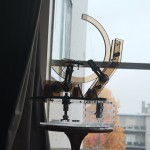
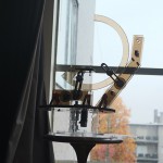
While I’ve been waiting for parts to arrive for Elapse, I’ve decided to build a companion rig that can smoothly pan a camera over the course of hours (or days or weeks or whatever). I’ve nicknamed it Relapse because it’s a repeatable camera gimbal, building on the idea of Elapse.


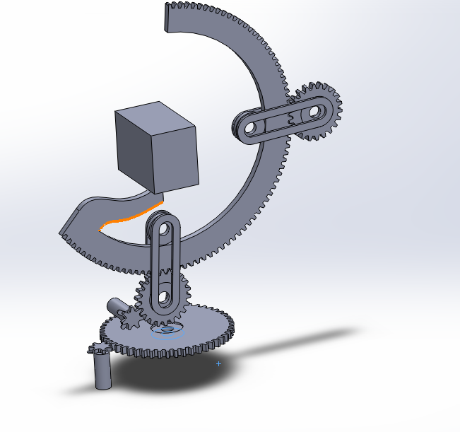
Here’s a quick idea I banged out for Relapse over the course of an evening. This shows the gist of what I’m trying to do, just without any of the structural elements (or gravity).

Prolapse Concept

Those cylinders are stand-ins for some geared motors that I have literally bags full of. That cube in the centre has the same dimensions as my small SLR camera.


After looking around unsuccessfully for cheap gearing that I can source locally, I decided to abandon that and go full-on laser cutter.


To do that, I had to have pretty exact idea of the dimensions of every piece I’ll need, and how it fits together. That’s a good opportunity to dive deep into Solidworks and make an accurate model of how this thing will end up instead of just a rough mock-up.

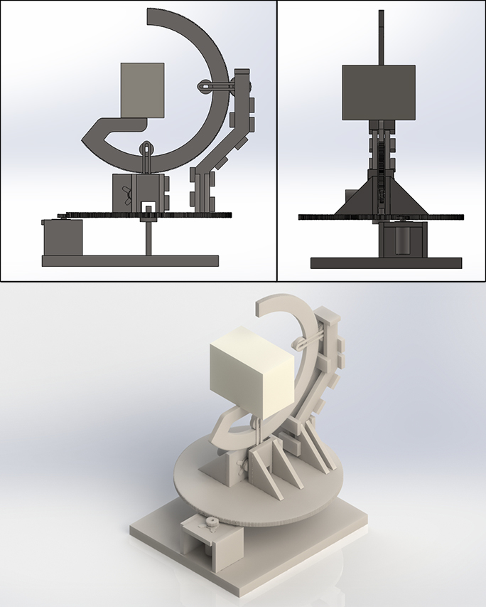
After a couple nights’ more of work and a trusty pair of digital calipers, I came up with this:

Final Prolapse Render

Click to make all your wildest dreams come true

Many of the pieces from this (the rails on the sides of the top gear and the bearings attached to them) are measured based off parts that I already have laying around. Using up excess materials is awesome, so that’s always a bonus.

Now I’ve got to pull it apart and lay all the pieces out for a laser cutting template.

Elapse

Shortly after I began building my clock, about a year ago, I got an insane job doing insane things for insane amounts of hours per week. Because I spend a lot of time on the road, I needed a more design-oriented project that I could bang out on my laptop for a long time without needing a soldering iron. So I pulled a new project from my bucket list.


Problem:

I want to play around with a time-lapse camera. Time-lapse mold, fungus, and plants growing look totally awesome, so I’ve decided that I want one. Most of the videos you can find on youtube or nature documentaries or wherever are done using a professional lighting rig, a DSLR, and an intervalometer. I don’t own any of those, and if I did, I wouldn’t want to leave my expensive camera in a spore-filled room for long periods of time, preventing me from using it for other things.


Solution:

Make a dedicated time-lapse camera on the cheap.


My progress so far:

Pretty much all of the materials have been gathered. An old digital camera has been sourced from Freecycle, the important stuff (lens assembly, control boards) fitted into a chassis. The schematic has been chicken-scratched into my notebook, and the PCB is ready to be etched. I’ve never done that before, so we’ll see how it goes. The PIC code is done, the design is laid out, I just need to build and debug everything.

Hopefully I’ll have some real progress soon.

The Mona Lisa

This is all you get, the circuit diagram is on one of my many many tattered notebooks in my workspace

Foiled Again

Pretty soon after I wrote that last post, I got sent up north for work for a long while. Which is great, don’t get me wrong, I like money as much as the next guy. It really limits my ability to physically build, though.

So I missed the contest entry deadline. Totally not surprised. I’d need another month to finish, but I’m putting this on the backburner for now.

So far, the only thing I’ve finished is the simulation. That may not sound like much, but let’s run through some numbers:

The design consists of 50 functional blocks representing (I think I counted right) 199 discrete CMOS ICs
The input, which is five words or 160 bits long, is clocked in 1 word at a time.
The output, also five words, pops out like magic 80 clocks later.
I haven’t done a proper timing analysis, but some back-of-the-envelope calculations (literally – I did this on the blank side of an envelope) give me a typical propagation delay of 545ns. This allows for a clock speed of about 1.8MHz, and tests about 22,000 combinations per second.

That’s pretty fast, and quite okay for a first draft. But it can be improved.
Right now, this circuit is set up into two cyclical stages. Only one input can be processed at a time as previous iterations of the data affects itself.
If the design were to be linearized, proper pipelining could make the design 80 times faster. There are also definitely some improvements to be had in designing for higher speed chips and in-depth timing analysis to figure out how tight you could get away with for pipelining.

But as I said; I’m killing this for now.

Shortly after I designed this, my harddrive failed and lost the original simulation files. I use cloud backup services now. Fortunately I had screencaps, though. Here is a pure hardware SHA1 encoder: