Archive for EDM

Hysterical

After building my Piccolo and playing around, I really don’t like the software. It’s certainly simple and hackable and does a lot of what I need to do, but something about the Arduino/Processing pair don’t quite work for me.

Fortunately it’s just a bunch of servo motors, and I already have the PIC code in my toolbox.

Using my Arduino-form-factor PIC dev board and my Bus Pirate as a computer-UART bridge, I wrote in a simple protocol to communicate.

The “communication enable” pin will go high, and then two (might change to three) bytes get sent. The first is an “address” or command, and the second (or second two) bytes are a value/argument.

The 0 address is X axis, 1 is Y, and 2 is Z. The Z only uses binary 1 and 0 for arguments.

The z axi has two states: active and inactive. Inactive/up is the parked position, obviously. The active mode has a hysteresis loop attempting to control the position. The feedback is wired up to a window comparator, like so:

On the computer side, I’m controlling the Bus Pirate with a Python script that feeds it one scalar for a given axis at a time.

The speed at which the PIC executes the movement is controlled in the processor, to be tweaked. I will probably add that command in, when it becomes cumbersome.

As more commands become necessary, I’ll be adding more to the processor, I guess. Maybe eventually I’ll implement a rudimentary G-Code.


Now for the fun part:


Part of my original design goal was to have a 10ns response time. That’s very fast. Most of the old monolithic MOSFETs I’m using (because they’re cheap) have turn-on times in the tens of microseconds.

That totally blows my requirements out of the window, but there are still some optimizations to be made. By using analog circuitry, I can directly control certain parameters and speed them up, compared to hitting a microcontroller and being a slave to a clock source and interrupts getting in the way.

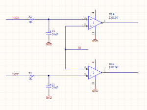
I’ve designed a window comparator. It looks like this:

Window Comparator

If the input goes above the “HIGH” voltage, then the top output turns on. If it goes below the “LOW” level, then the bottom output turns on. There will be two of these circuits. Feeding these outputs to some discrete logic, or something clever that I haven’t thought of yet, I can turn on or off transistors to the different power stages.

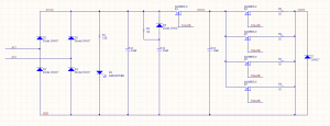
EDM Schematic V2

There are three power stages: Stage 1 (rectified input), stage 2(charge), and stage 3 (output).


The S2 MOSFETS can be ignored, just treat them as one. I should be able to parallel as many as I need, within reason, it doesn’t change (most of) the math.


The input of one window comparator is from VOUT, and the outputs are hooked up to the micro. If the HIGH output is on, then that means the MOSFET Q2 is on, but the EDM electrode has not made contact with the workpiece. Start (or continue) jogging the Z axis down.

If the LOW output is active, then we’ve gone down too low, start jogging up.

The other comparator’s input is at S2VCC. That controls the turn-on and turn-offs of the MOSFETS. If C3 is too low, then Q2 must be shut off and Q1 turned on to charge it up. When it is high, flip that. The idea is that Q1 and Q2 should never be on at the same time, providing a direct path to ground. The logic here will also involve halting the Z jogging, or making it jog up.


So there you go. With two different kinds of hysteresis going on at once, there will be some experimentation going on with how they work together. That leads me to one last trick:

You see the HIGH and LOW inputs on the comparator circuit? Those must be an analog voltage. That I’m going to set with a PWM out on the micro and the caps smoothing it out to an analog value. Varying the duty cycle of the PWM will allow me to vary the analog voltage.


Counting up my PWM outputs:

Two for each window comparator (4 total)

One for each axis (7 total)

One for the oil pump (8 total)


I haven’t discussed that last one yet, but stay tuned!


CNC Day

Aw yeah, CNC day.

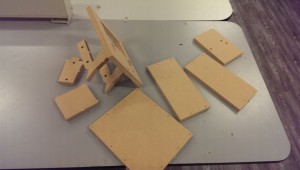
CNCed Tank

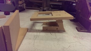
Pretty simple parts, I guess it wasn’t strictly necessary to use a CNC, but hey, it was there.


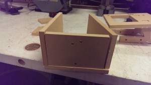
Here it is coming together.

Tank Test Fit


A spaceship!

CNC Spaceship


~~~~

Brief interlude

~~~~~~


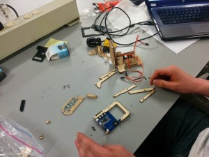
Laser cut Piccolo parts.


Piccolo Assembly


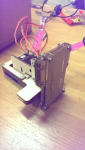
And the rest of it.

Piccolo Assembled

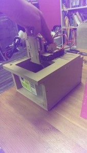
Rough-ish final box.

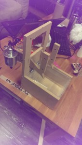
Small EDM Tank

And it flips up!

EDM Tank Up


So the next step is to figure out a way to mount the Piccolo on top of the box as shown. There’s a little bit of MDF I need to cut away to make it fit better, too.


After that, I need to modify the Arduino sketch (ugh) to jog the Z-axis up and down to keep the electrode in the conductive region.

First Burn

During my research on how others have handled the sparking circuit in an EDM, I’ve been fairly unimpressed. Off the top of my head, there was one 555-based pulsing EDM circuit, one purely analog circuit that was never built, and one hand modulated system attached to a drill press.

It’s hard to tell exactly what will make a winning design, so I’d rather not hamstring myself with fixed logic that may or may not be ideal. And for the first few iterations will almost certainly fall on the “not” side of that line.


What I’ve settled on (and indeed, what my education is in) is computer control. Small microcontrollers have gotten fast and cheap enough that there is very rarely a reason not to use them, other than bragging rights or very high volume manufacturing.


That’s a little bit unfortunate in some cases, but it’s great for this one.


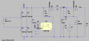
Here’s a first third draft of the circuit I’ll be using. I had a few false starts, but this one is the first one I actually (mostly) drew out, and it seems to work. I used two power supplies in series to get 60V and breadboarded it up. Not the final 80V supply, but close enough.

EDM SPICE

I only simulated the first stage (and with the wrong optocoupler!) but it proved the concept.


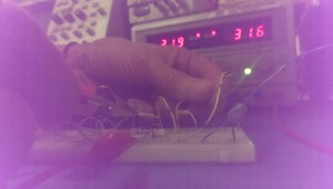
So I got my first burn last week to prove the concept! I tried to get a picture of the sparks, but it was tricky with my crappy phone camera. I was totally welding wires together, though, it was awesome. In theory, that shouldn’t even cause excess wear on my components or power supply. Everything is well within spec.

First Burn


I’m a little but worried about the speed of my components. I’d like to be able to get this pulsing in the 20ns range, but I’m pretty far away from that, I believe.

The two important components in this are the H11D3 optocouple and the IRF9540 P-Channel MOSFET.


According to the datasheet, the transistor has a rise time of 73ns, which right there blows my timing requirements. It has a turn-on delay of 16ns which also isn’t fantastic. That’s 100ns just for the transistor.


The optocoupler is worse, however. About 5 us. I’m not familiar enough with them to know if that’s a good value or not, but I’ll look at my options for rev 2.

Worth noting that this has a base connection, which doesn’t seem to make sense, given that the optical input is basically the base.

From here, though:

Click to access an3011.pdf

It looks like it’s to my advantage to use the base! It’s floating for now, but I’ll tweak the values to get to the most out of it when I have a scope on it.

Start small.

Other than wanting to spend very little money on this project, the scope of it is huge enough that I’ve been trying to use as many prebuilt components as possible.

If I have the majority of the project build with discrete, modular components, then I can start drilling down and replace the weakest links, one at a time.

Because the CNC portion is horribly complicated, and itself comprised of several parts (drive electronics, mechanical movements, control software, firmware), several weeks ago I made the decision to use a low-cost CNC platform. I mean “platform” in the sense that it’s designed as a starting point to hack, redesign, and improve.

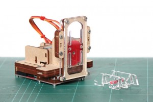
It’s called the Piccolo:

piccolo stock

It uses three (TINY!) servo motors, a bunch of laser cut gears and mounting plates, and some Processing-based software. Everything is open-source, and I don’t think they even sell any of the components themselves. They provide all of the files and expect people to make it on their own, which is kinda cool.

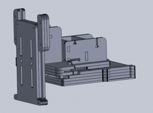
One thing I couldn’t find on their site anywhere was the work area. I needed dimensions of all of the parts to mount and design around this anyway, so a couple hours with their laser cutter files produced this:

piccolo model

Turns out all axis have a range of about 2.5 inches. That’s really tiny for a CNC platform, but definitely usable for making PCBs. At first, anyway. That double-ensures that this portion will eventually be replaced, probably with a CNC system of my own design. That will be fun, I am looking forward to it.

One note for future-self:

There is a decent chance that the sparking from my electrodes will cause enough interference to mess with my servos. If they get really jittery during a burn, I know exactly what is happening, and a redesign will happen sooner rather than later.

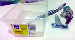
Working with the above files, I gathered together some more materials:

EDM Tank Supplies

A 12V oil pump($12) for the EDM fluid (more on this in a future post), a standard heavy duty door hinge($3), and a small plastic tank($0.89). The tank is a lot smaller in person than it looks.

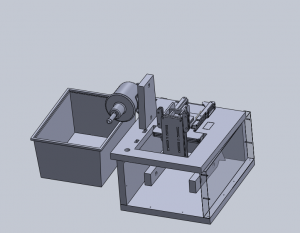
Putting it all together:

edm tank model 1

That’s a reasonably accurate mode of the tank on the left.

There’s also models of the Piccolo and the fuel pump that you can see there.

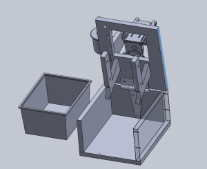
The rest of the frame is designed out of 1/2 inch MDF. The tank fits in the box, which can flip up like so:

edm tank model 2

And BAM. Hinges. The idea is that the whole mess can flip up for servicing, changing out the PCB, etc.

The PCB holders at the bottom might be changed a little before I build this, but the idea will stay the same. They’ll be submerged in the EDM fluid in the tank during operation. Afterwards, the top flips up, and those PCB holders are angled so that the oil drips back into the tank.

That should mitigate oil going everywhere somewhat. I still expect this to get messy.

EDM Prime

One of my theories for rapid PCB prototyping is EDM, or electro-discharge machining. The idea behind EDM is that you have an electrode hooked up to negative voltage, dunk the system in a high impedance fluid, and then put a potential on the metal workpiece. When that electrode is close to the metal and the potential is high enough to ionise a path through the dielectric fluid, an electric arc gets created between them, taking out a chunk of your workpiece.
Basically a spark welder to remove material.
This is often used for removing broken taps from holes or machining very deep, narrows holes with high precision.

I think I can use this to directly erode paths between traces on a sheet of copper-clad.

EDM is one of those strange niche tools that only machinists are really into. The hardcore kind of machinists that don’t really internet well. There seem to be about three resources on the internet for details on the inner workings of these machines: one CNC forum, one thread of a 3D printing forum, and one Yahoo group. None of these are particularly fantastic.
Fortunately, machinists are a lot more into books. Robert Langlois put out a couple how-to manuals in the early 2000s, and Ben Fleming has some much more recently.
Someone got in contact with Langlois recently, and relayed that he lost interest in the project, would definitely like to see Raspberry Pi control of an EDM, and is open sourcing his books. So, naturally, I’ve read those books. I’ve also found some academic papers and expired patents that go over some design constraints.

There really are three major building blocks in building one of these: a CNC platform, the dielectric fluid immersion tank, and the electronics. The mechanical guys have got the first two figured and polished to a degree that I’m not capable of. The circuitry, though, is all extremely simplistic. I think I can add some microcontroller controls and improve hugely on the designs.
Most of the EDM schematics out there are just rectifiers and 555 timer-based pulse circuits.
One of the more sophisticated designs out there, The Garden of EDM by C. Scott Ananian provides an excellent rundown of design decisions, and has some similar ideas to what I’ve come up with independently. His version seems a unnecessarily complicated, though. Especially considering he never actually built his circuit. I’ll start with a much simpler design, offload more to a microcontroller, and end up with more control out of the deal.

Here are some parameters I’m trying to hit:
20-100kHz pulses
20ns rise times or better
Adjustable voltage up to 80VDC
4 amp current max

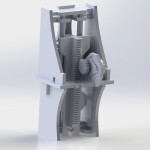
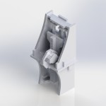
That’s enough substanceless discussion for now. Starting with sink-EDM, the circuitry and mechanical Z-axis go hand-in-hand. I sat down for a few hours and built something in Solidworks:

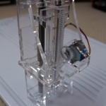
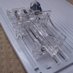
After another few hours, I’ve got it laser cut to get this:

Man, clear acrylic is really hard to photograph properly. Everything was cut on a single try and slotted perfectly into itself on the first try. I’m really quite pleased. The rails are scavenged from an old scanner.

And then alongside that, this is the very first draft of “maybe what I’ll build, unless I have some better ideas”:

EDM Schematic V1