Archive for Projects

Declarative Statement Goes Here

As I sit here, riding shotgun in my work truck on the way to a job site, there is very little that I can do to be productive. I feel like I’m wasting my time.
What I can do is set some final goals for my project, and also maybe do some some musing (in the most pretentious language possible).

But first, some background:

As implied, I spend a lot of my time working on the road. That means a lot of cheap motel rooms, and a lot of unreliable internet access. When you’re stuck for the coldest six weeks of the year in the township of Bumfuck, Northern BC, internet access becomes pretty important.

As often as motel wifi is flaky, my internet-enabled devices can usually see a password-protected residential network nearby. Naturally, trying to break into someone else’s router would be immoral, but it does present an interesting problem. How easy would it be to make a portable wifi cracker?

To make a long story short, I decided to make a very fast WPA-PSK brute forcer. “Very fast” is a little misleading here, because despite potentially having the ability to test hundreds of passwords a second, breaking a properly chosen password is not something that can be done while you sit around and twiddle your thumbs. It takes a little longer. Think “aging a good cask of scotch” timeframes.

By this point, the problem has become purely academic. But that’s okay. I decided to do it anyway. But just as I settled in to write some serious VHDL code, the 7400 competition reared its beautiful head.
So I decided to do something slightly insane and drop the FPGA.

I’m designing a CMOS SHA1 encrypter. The PBKBF2 and MAC portion of WPA2’s encryption scheme won’t be done, the SHA1 will stand alone.

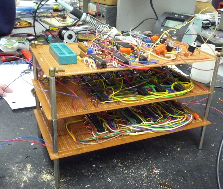
Insane quantities of chips aren’t without precedent for me. My final project in school was a poster child for function creep.

It didn't work.

Fig 1: This is what happens when you let the team member with Aspergers add “just one more thing”


As I start to get my teeth into this project, I’m coming to the realization (hope) that I don’t have 16 straight hours of soldering in my future. While there are 512 bits for the input, and 160 for a default seed, and then another 160 for the output, and also a clock source that has trigger each stage sequentially- wait. That does seem like a lot of soldering.

Fortunately, my requirements are pretty tightly defined so not a lot of function creep is possible. There’s only the problem of reliably verifying that the board works by passing the 16-word input and reading the 5-word output. I’d use an Arduino and some shift registers, but I don’t have any ATMegas with bootloaders on them. Maybe I’ll use a PIC and RS232 with a MAX232 and some custom Windows software…

Oh man.
I am in trouble.

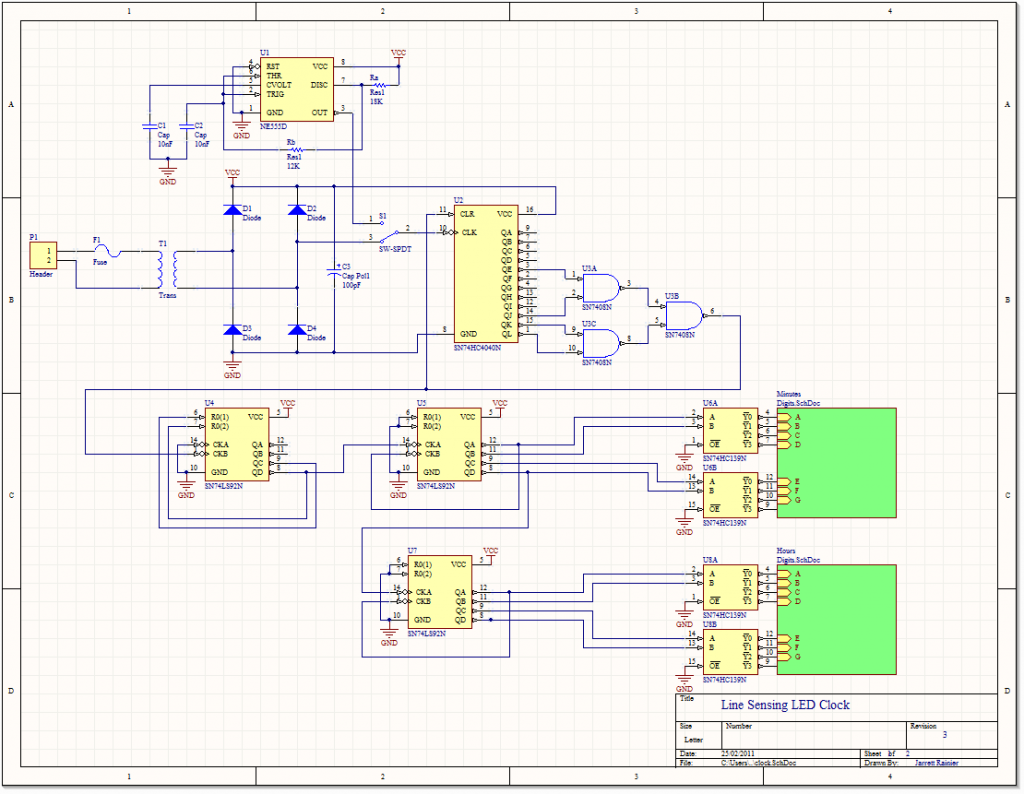
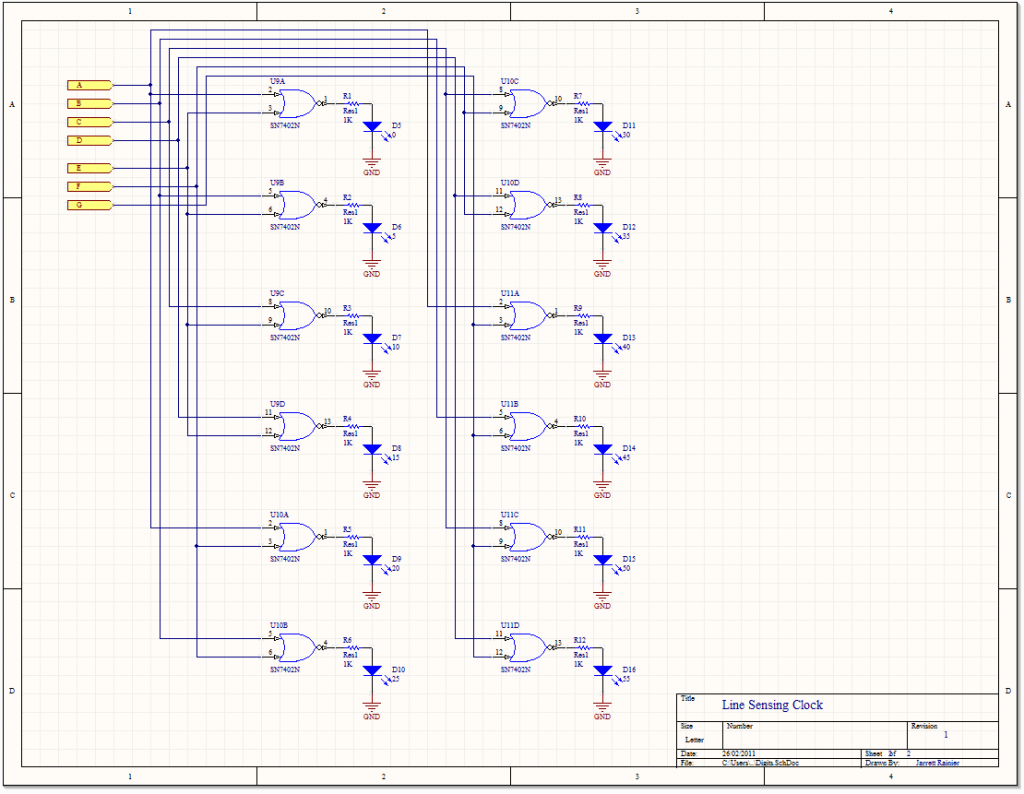
The Schematic

Part 1

Getting the time.

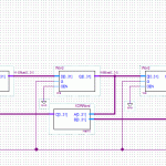
Adhering to my “don’t buy anything” policy for this project, I’ll be using the 5V charger for my old Motorola Razr for power. I’ll have to open it up and find a stepped-down voltage that hasn’t been rectified yet. Then I can use divider chips that I have on hand to get the frequency I need.

Setting the time.

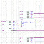
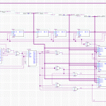
The “set time” switch toggles the clock input of the counter chip U2 from the 60Hz line voltage to the much higher frequency 555 circuit.

I’ll set the frequency to, say, 3600Hz and the capacitor to a common value of 10nF, then Rb = 12kΩ and Ra = 18kΩ.


Things that I could do better (but won’t):

  • The switch isn’t debounced. This is bad. Every time you hit the switch, U2 will get clocked several times due to the switch contacts bouncing. The likelihood of this unexpectedly advancing the time is only three or four times in every 360.
  • A much better way of setting the time would be to use pushbutton to cause a monostable 555 sending a pulse to an astable 555 long enough to clock U2 360 times, advancing the minute hand by one. And something similar for the hour hand, too.
  • A potentiometer could be used instead of Ra or Rb, allowing the user to adjust the speed of the minute hand.


The Premise

Sometimes I build something because it’ll be a fun challenge, and sometimes I build something because I need a pretty clock. This is the latter of those two scenarios.


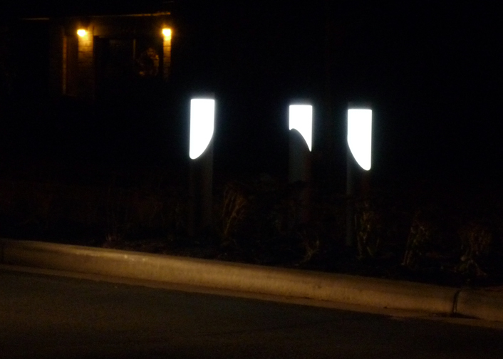
This was inspired by a series of lights in Burnaby (on Moscrop near Willingdon) that seem to be lit by blue LEDs behind frosted glass. The effect brings out the 12 year old girl in me, and I can’t look away. They’re so pretty.

Just pretend that my camera could pick up the blueness


So I’m going to build an analog-style clock that displays the minutes/hours using blue LEDs behind frosted glass (or plexiglass more likely). Because I hate batteries, I’ll have to use AC wall voltage, and because I am economically challenged, I’ll restrict myself to using components that I already have on hand. The exception to this rule is the large amount of LEDs I’ll need, but I’ll burn that bridge when I get to it.


Some background:

Your AC wall outlet is oscillating at about 60Hz. It’s not operating at exactly 60Hz because 100% accuracy is not possible. Ever.

However. BC Hydro knows their target frequency, and they know how many seconds are in a day. So what they do is they keep track of how many oscillations they generate in a given day, and in the wee hours of the morning, they speed up or slow down their output frequency. The end result of this is that while your wall outlet is only approximately 60Hz, it is exactly 60Hz on average.

Using this to my advantage, I can make the clock’s, er, clock frequency based off the 60Hz line voltage, making my clock never lose accuracy, power outages or DST aside.


I’d like to provide an alternate, higher frequency clock that can be swapped in with a switch to let me set the time. Because otherwise I’d have to wait up to 12 hours and plug the thing in at just the right moment.