Archive for Projects

Summertime, and the livin’ is easy

People often ask me, “Jarrett, what is the Best Thing in Life?”

I’m not sure why people keep asking me this, but depending on my mood, the answer is one of two things: Floating on a lake, or swinging in a hammock. At peace with the world.

Frustrated by this bounty of choice that I just couldn’t narrow down, I began righting this wrong in the world.


So I bought a boat.


And I bought a hammock.


And I bolted them together.


It even got me a sweet discount on the boat.


In truth, it actually took several false starts to build this successfully. Part of the challenge was that I wanted to avoid making any permanent modifications to either of the two structures, and the other difficulty is that while mulling over the challenges, well, I had a hammock in which to ponder design decisions. It’s nigh impossible to exit a hammock once you’ve settled in: fact.
The hammock frame is made out out of steel tubing, but the pontoon boat’s frame is aluminum. This made things a little challenging. No welding, really.


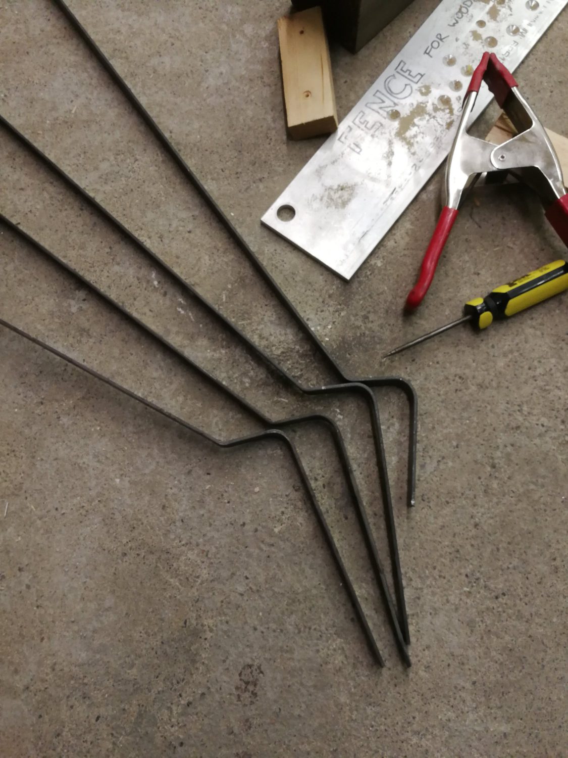
My first attempt used some steel flat stock.

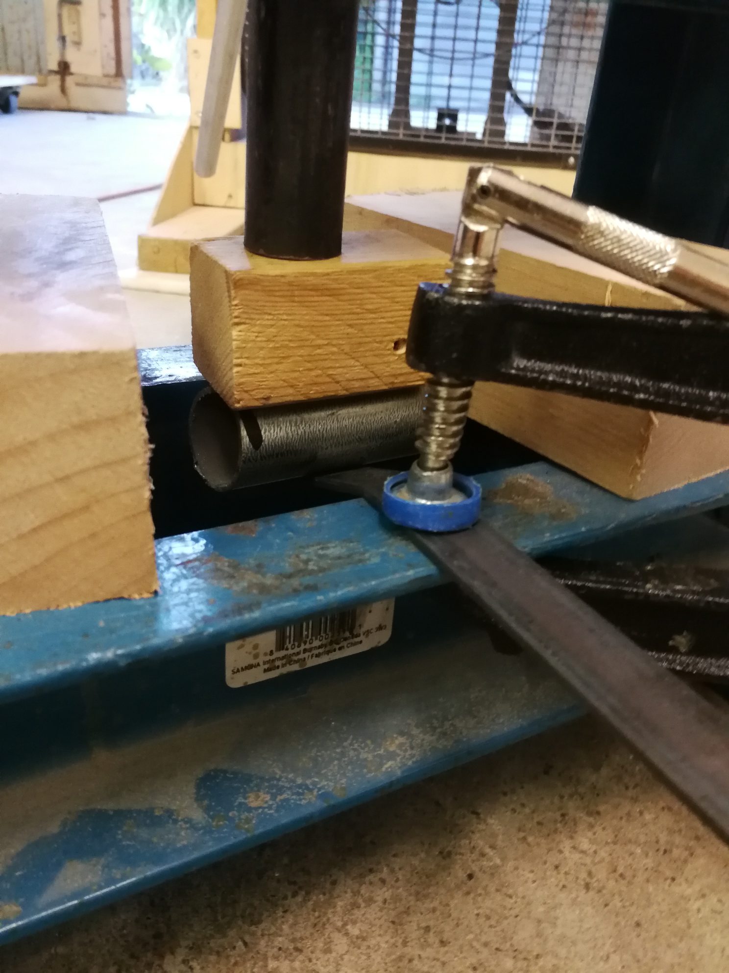
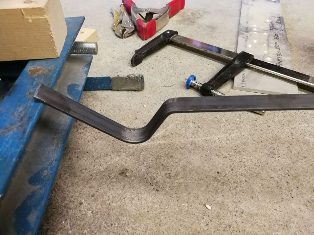
I used a hydraulic press in an only sort-of-sketchy set-up to bend them in a half circle to go around the hammock frame’s steel tubing.


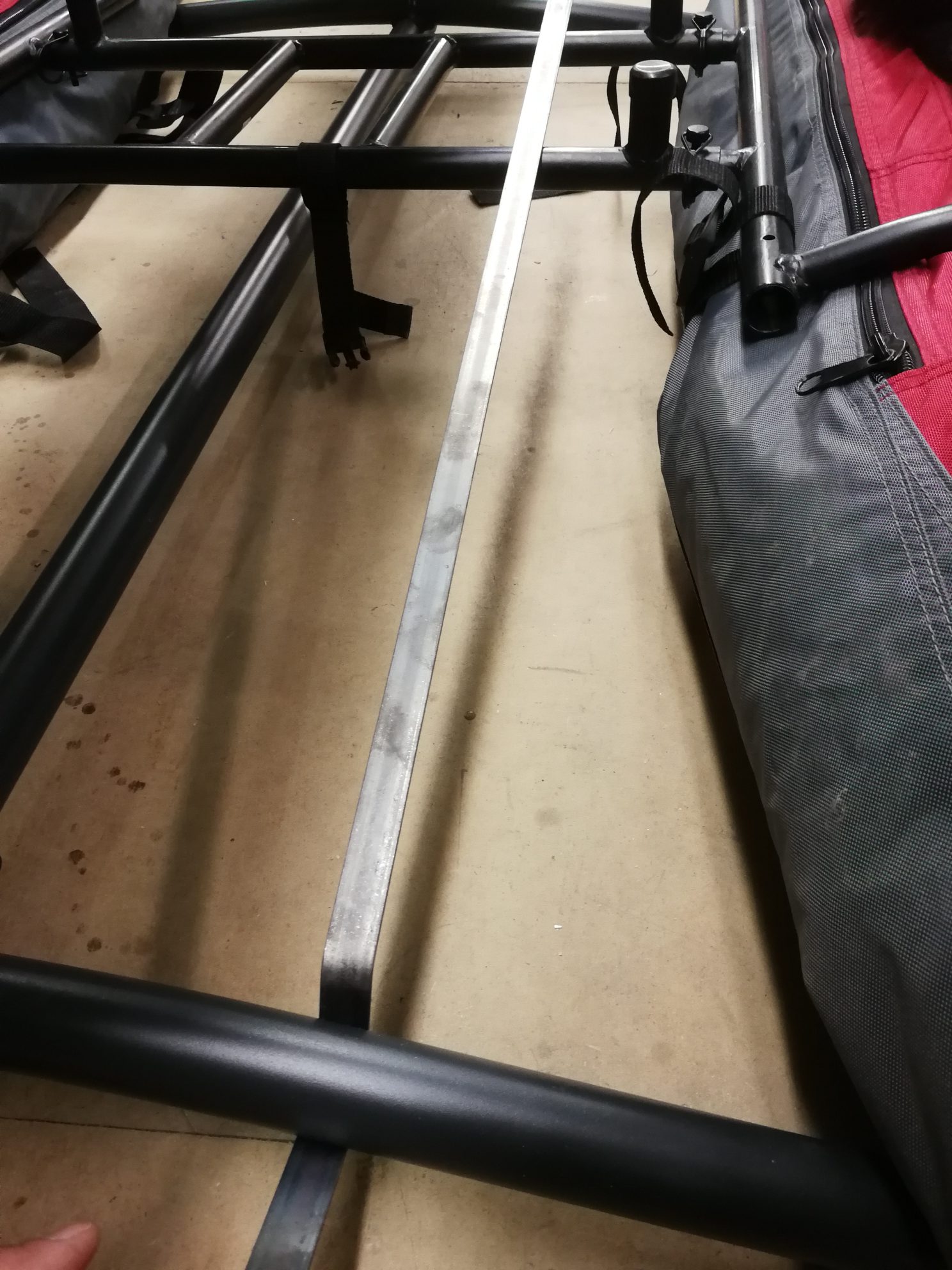
While putting any kind of weight on these, they’d bend distressingly, and have a sort of spring effect that I could see multiplying forces in weird ways, so I decided to abandon that route.

That made me sad, though, look at those bends!


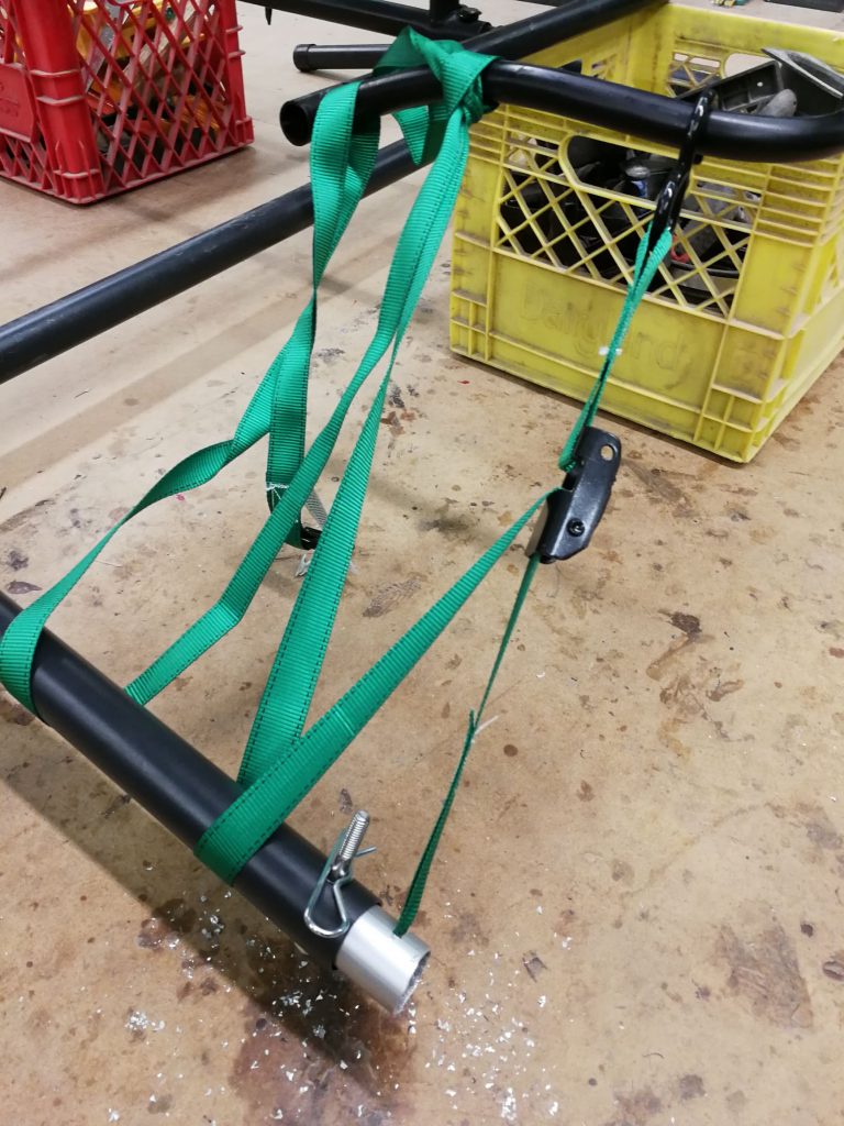
In parallel with the above, I also picked up some straps and built a method to fasten them around the pontoons.
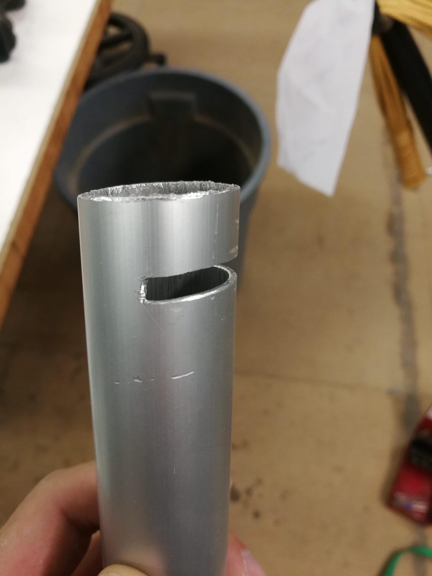
Aluminum tube, a slit, and some filing (oh so much filing) did the trick, along with some new holes, bolts, and cotter pins.


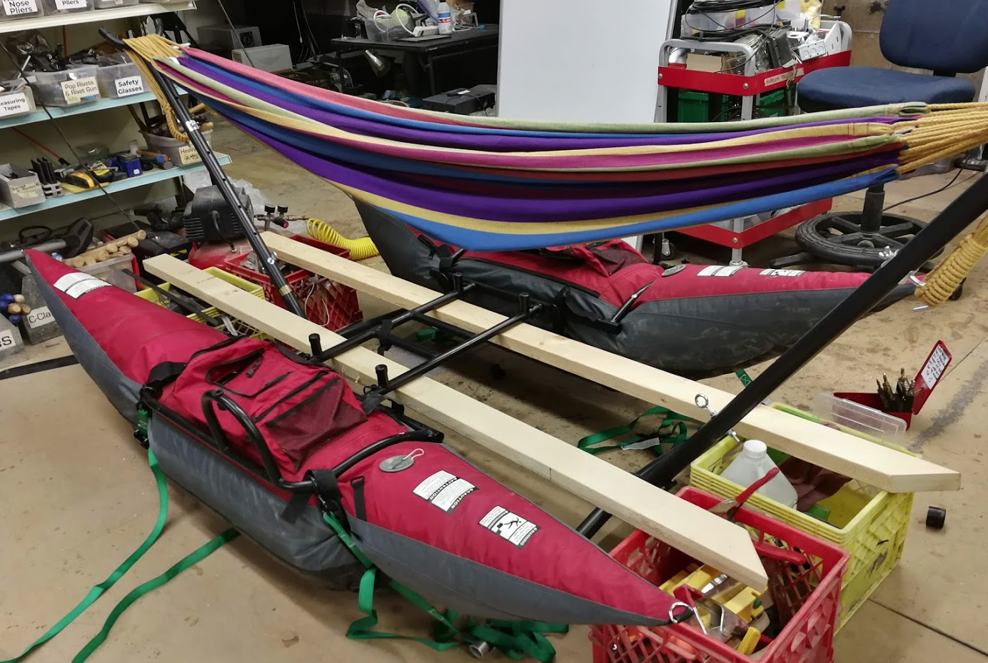
Also positioning the whole contraption without mashing the pontoons against potentially sharp machine shop floor was tough. I finally settled on this lumber solution, which helped me see the final fastening solution.


Back to the scrap bins, I found nearly the identical black anodized aluminum tubes that the pontoon boat is made out of. They slot right into the existing frame and couldn’t be more perfect. I hear they’re from an old bedframe.

First I tried to bend one.


Then I tried harder to bend it.


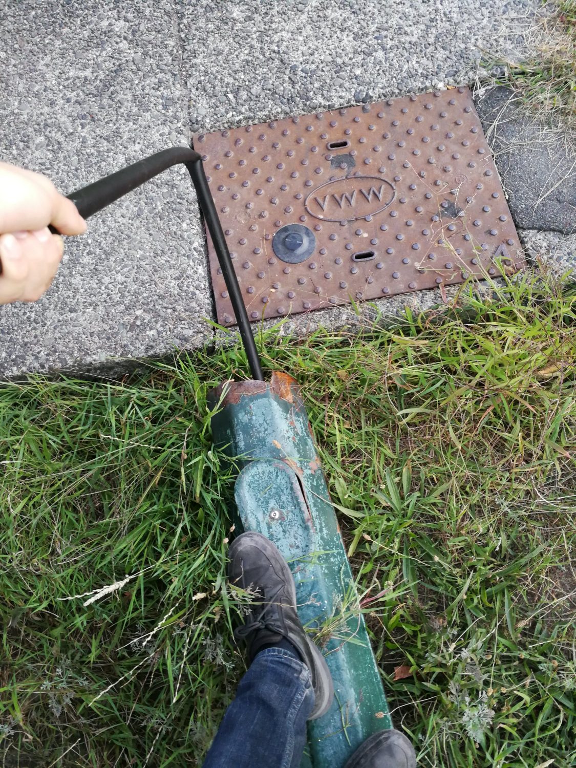
Naturally, I kinked it, but I continued to try to bend it, this time using a convenient streetlamp garden decoration.


I still couldn’t get the bend angles I needed! Just not strong enough or heavy enough or clampy enough! I abandoned that attempt.

So attempt number, whatever.

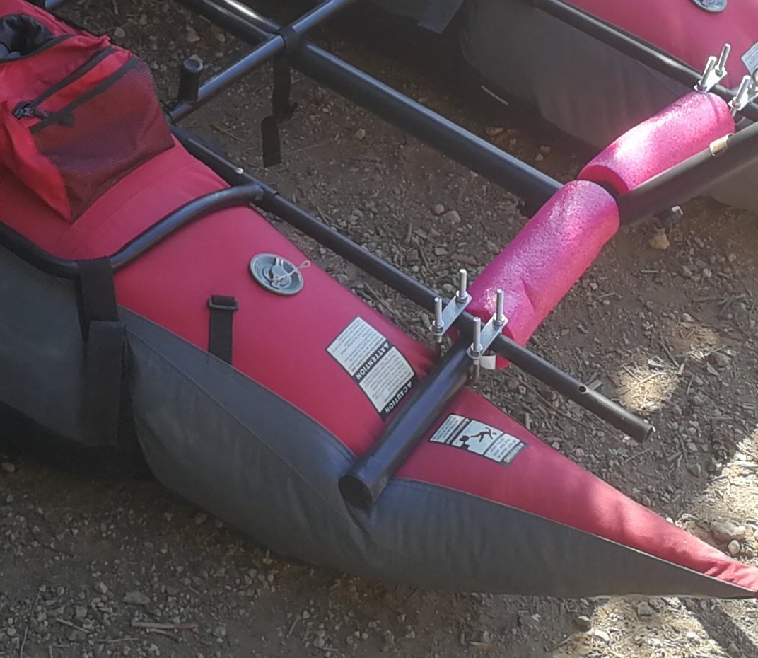
I tossed two more of those scrap tubes into the boat frame, and clamped it on with some u-bolts.


Well that was easy. It brought the hammock a liitttle higher than I really wanted, but I decided to gopher it and fix it in rev 2 if it was a disaster. Summer is running out.


Before launch day, with much thought and much more relaxing hammock meditation, I decided that the boat tooootally had enough side-to-side stability, and that I’d have more issues front-to-back. This is because the hammock in resting position really wasn’t too much higher than the original boat’s seat, but the leverage on the hammock’s front/aft mounting points was way further out than the pontoons.
This later turned out to be completely correct.

But, burn that bridge when we get to it! I will probably add an outrigger to the back of the hammock frame. The water wings and pool noodles are not intended to be used, they’re just there as a last resort hammock rescue device, which we didn’t need.

And grab a couples friends and off we go.


Here’s the maiden voyage:


Spoiler:


But with a little more careful weight distribution, it works! It actually works really well, I was kinda blown away. It’s pretty much the best thing ever and I can’t believe it didn’t kill me.

Bliss.

POV Globe – The Mechanicals

The mechanical design for this project follows the “as quickly and easily as possible” maxim even more so than any other section. I used flat pack laser cut design strategies that results in pieces that snap together. I like that because it could in the future be turned into a kit reasonably easily, and in the meantime, it’s just a quick way to design and iterate.

For this first version, aesthetics plays no part, I just wanted to get the PCB mounted and spinning, along with an appropriate motor.

I used off the shelf mechanical components wherever possible, too. Standard bearings, shafts, collars, and couplers. Oh my.

Coupling the PCB to the drive shaft was a challenge that went through a few ideas to keep it manageable. Something off the shelf, or quick and cheap to manufacture. 3D printing is right out. This picture illustrates the problem, along with a laser cut mock up of the PCB:

One of the solutions I explored was to use clevis pins, intended for RC helicopters.

I found some aluminum ones and some nylon ones, but the former ended up being unsuitable for size. The nylon still wasn’t perfect, but here’s a tip for when your shaft is inappropriately large:

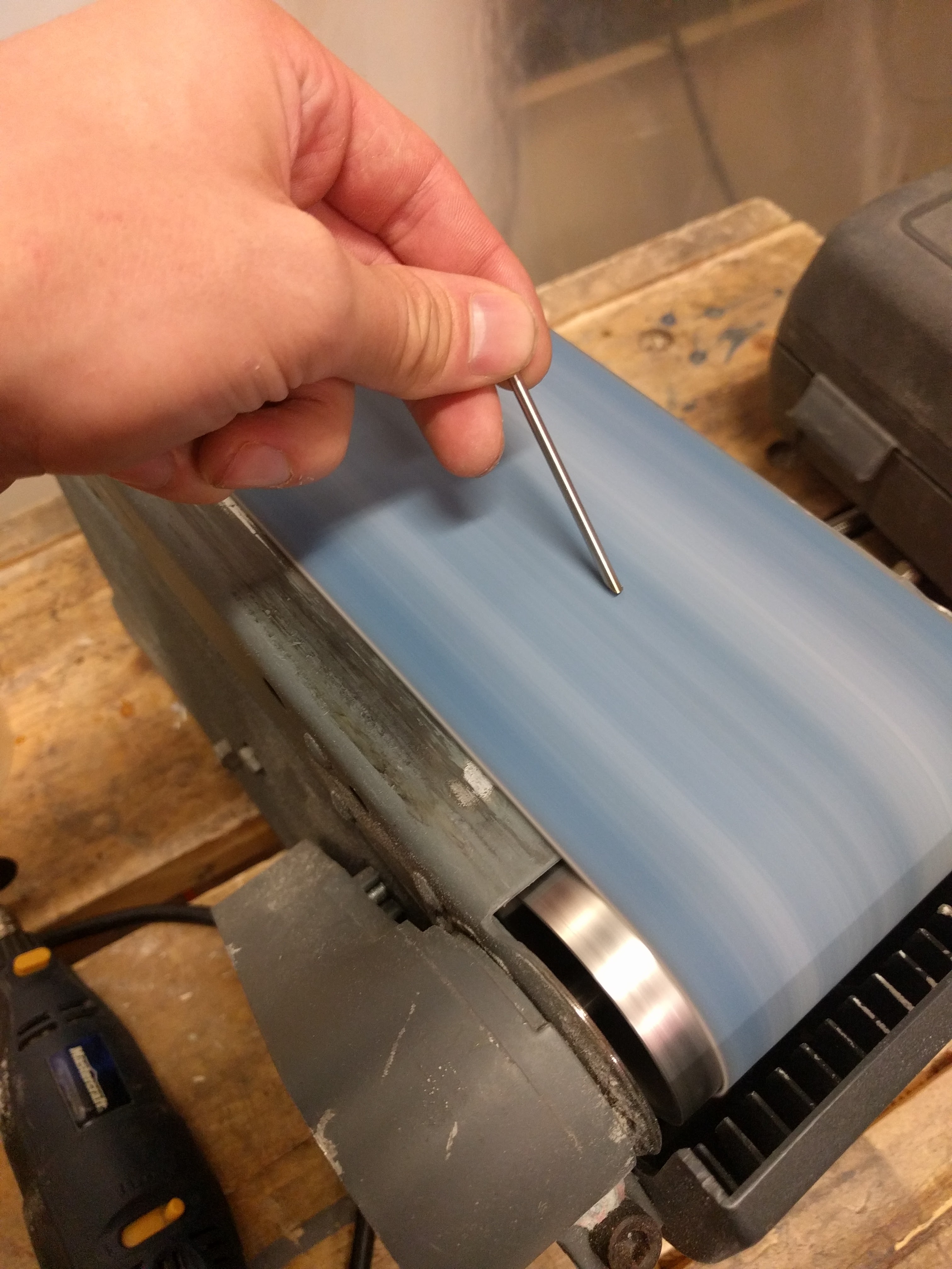
You can grind down steel rods to make a serviceable cutting edge, turning it into a poor-but-functional drill bit. Then they’ll drill right into the nylon.

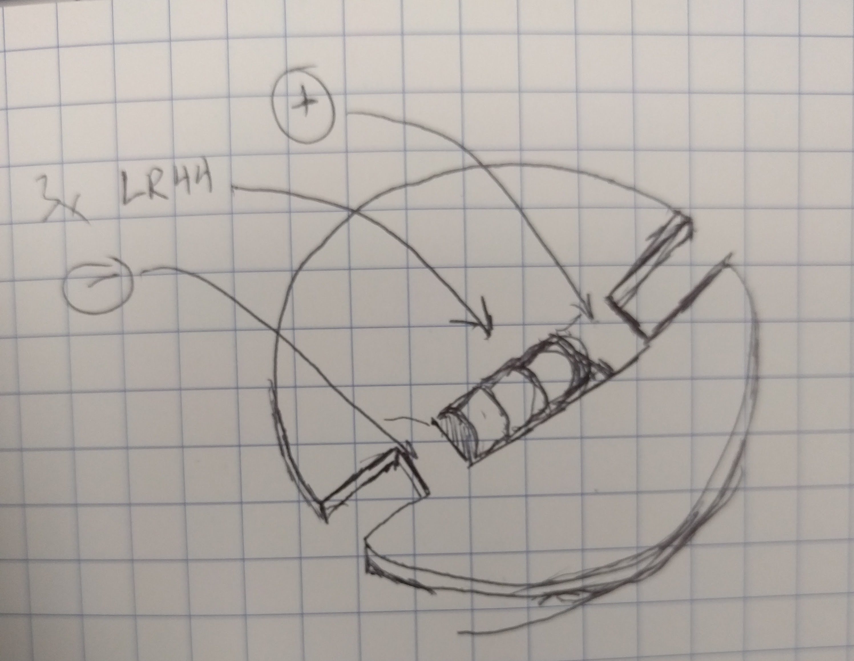
One more issue was battery holding. Ideally, I wanted a cylindrical battery (or batteries) held longitudinally in the centre of the sphere. That seemed best for keeping the spinning disk balanced. For electrical reasons, I chose three LR44 coin cells stacked up to make 4.5v nominally.

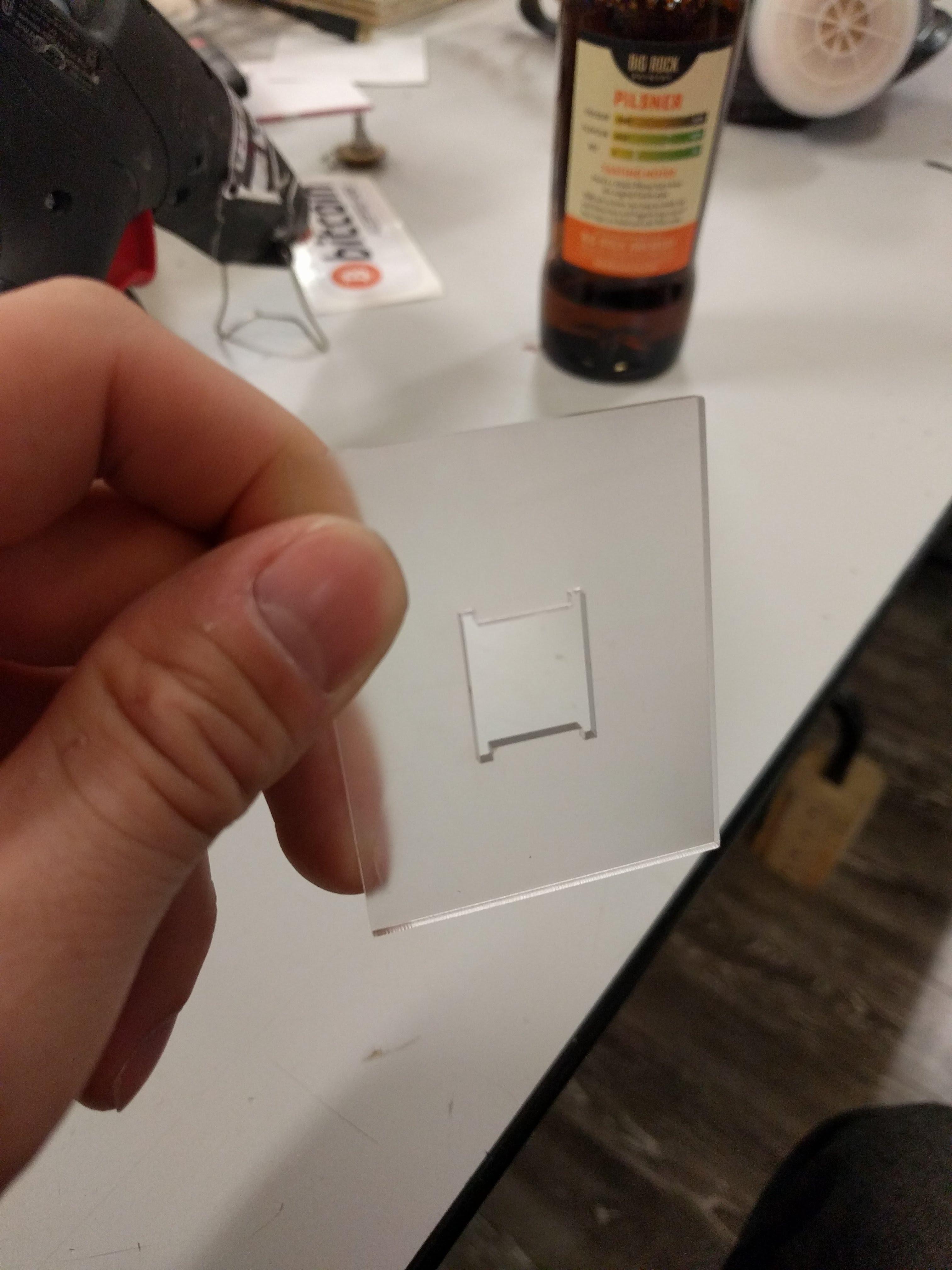
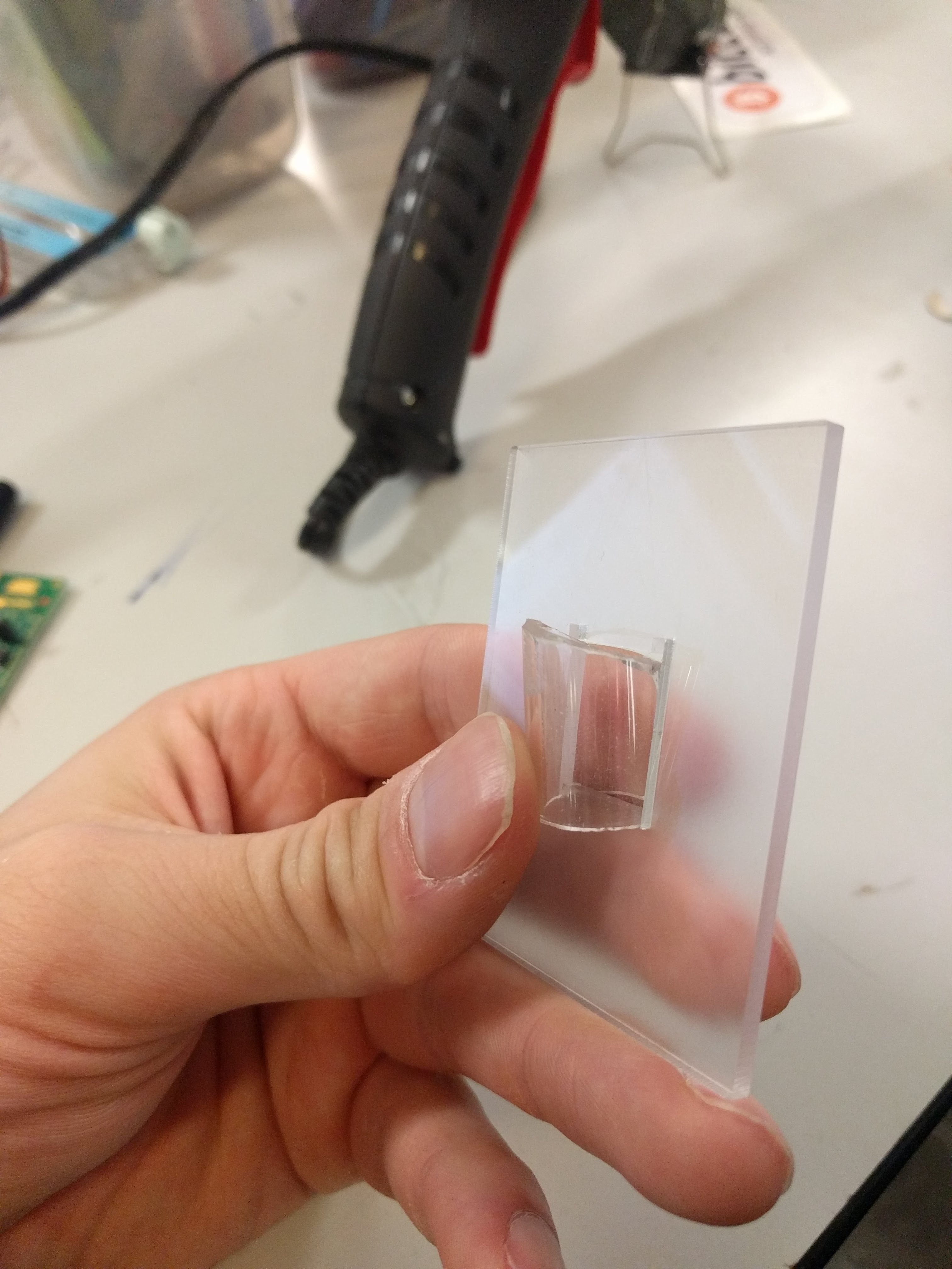
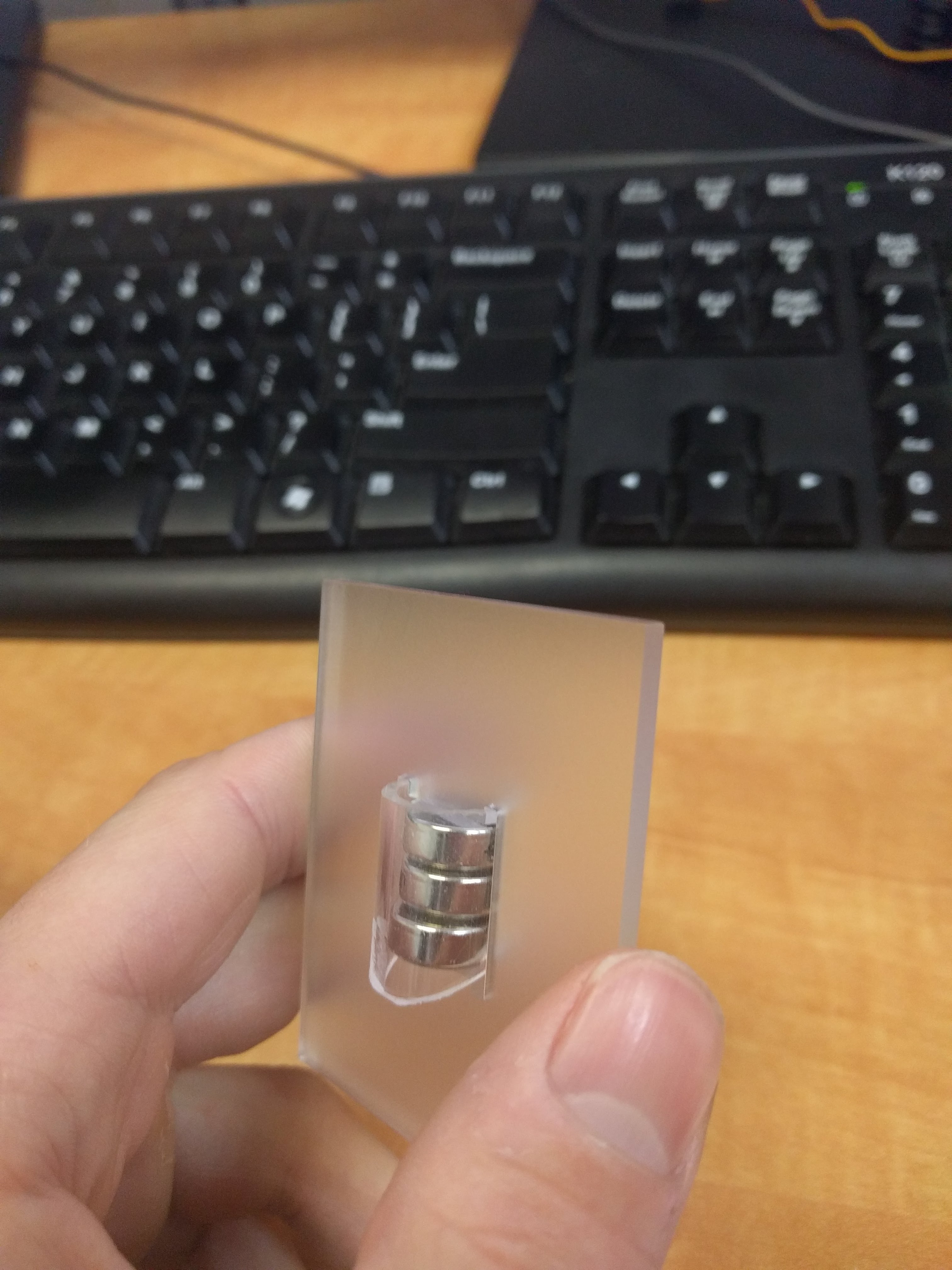
After much fruitless battery holder searching, I grabbed a 12mm ID acrylic tube, and cut away part of it such that it could be fit into the PCB and then twisted to lock it in place. Like so:

That actually locked together pretty solidly, and I added a battery spring to the PCB to hold the batteries together.

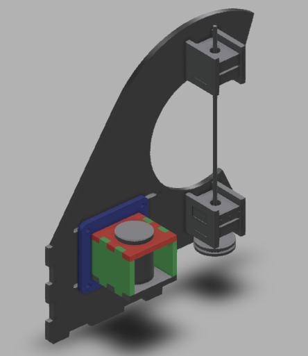
For the overall frame, I tossed something together in Fusion 360:

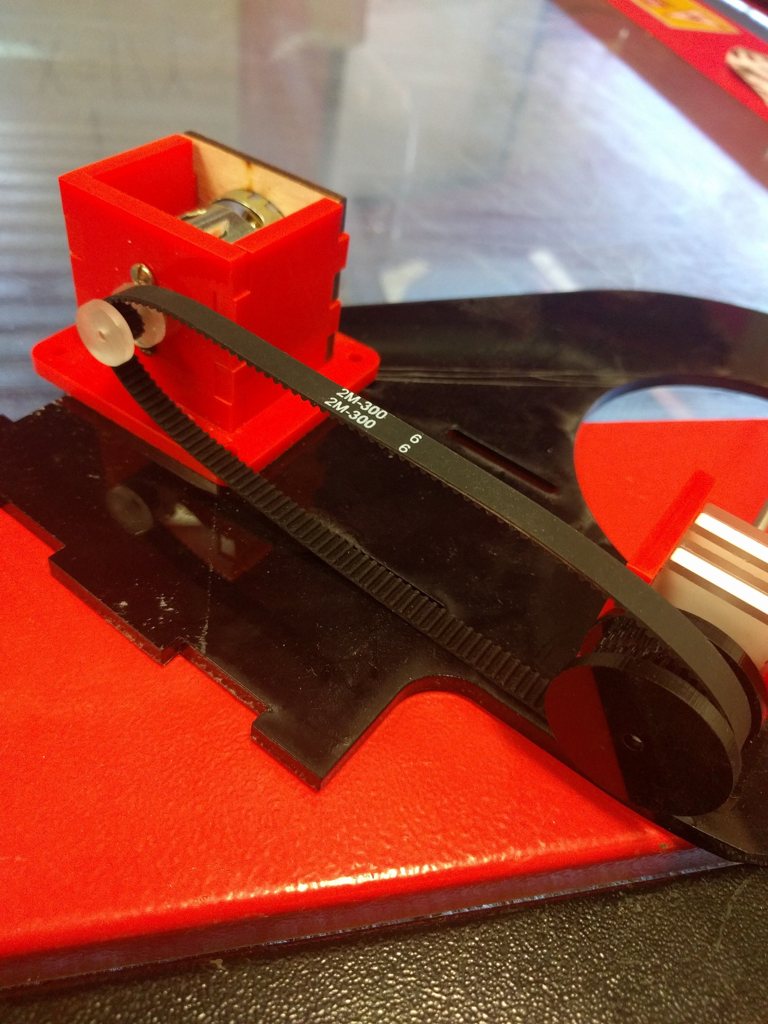
With the very first cutting, made from totally scrap laser material – mostly acrylic, but some plywood in there for good measure – I found a minor setback: I had the wrong belt size.

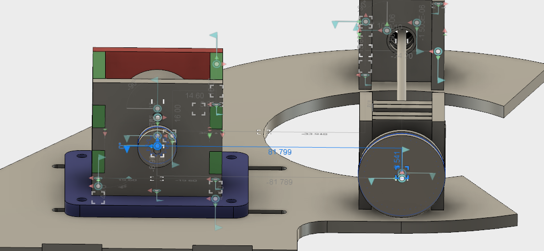
I’m not sure if I calculated wrong the first time, or did some redesigns after purchasing my belt or what, but a second calculation did confirm that my on-paper expectations should have matched my physical fit. I had a 300mm belt, but 82mm between centres at the middle of the adjustment distance, so there was no way that was going to fit.

A 200mm belt proved much more suitable and revealed the next issue, which I vaguely suspected would crop up.

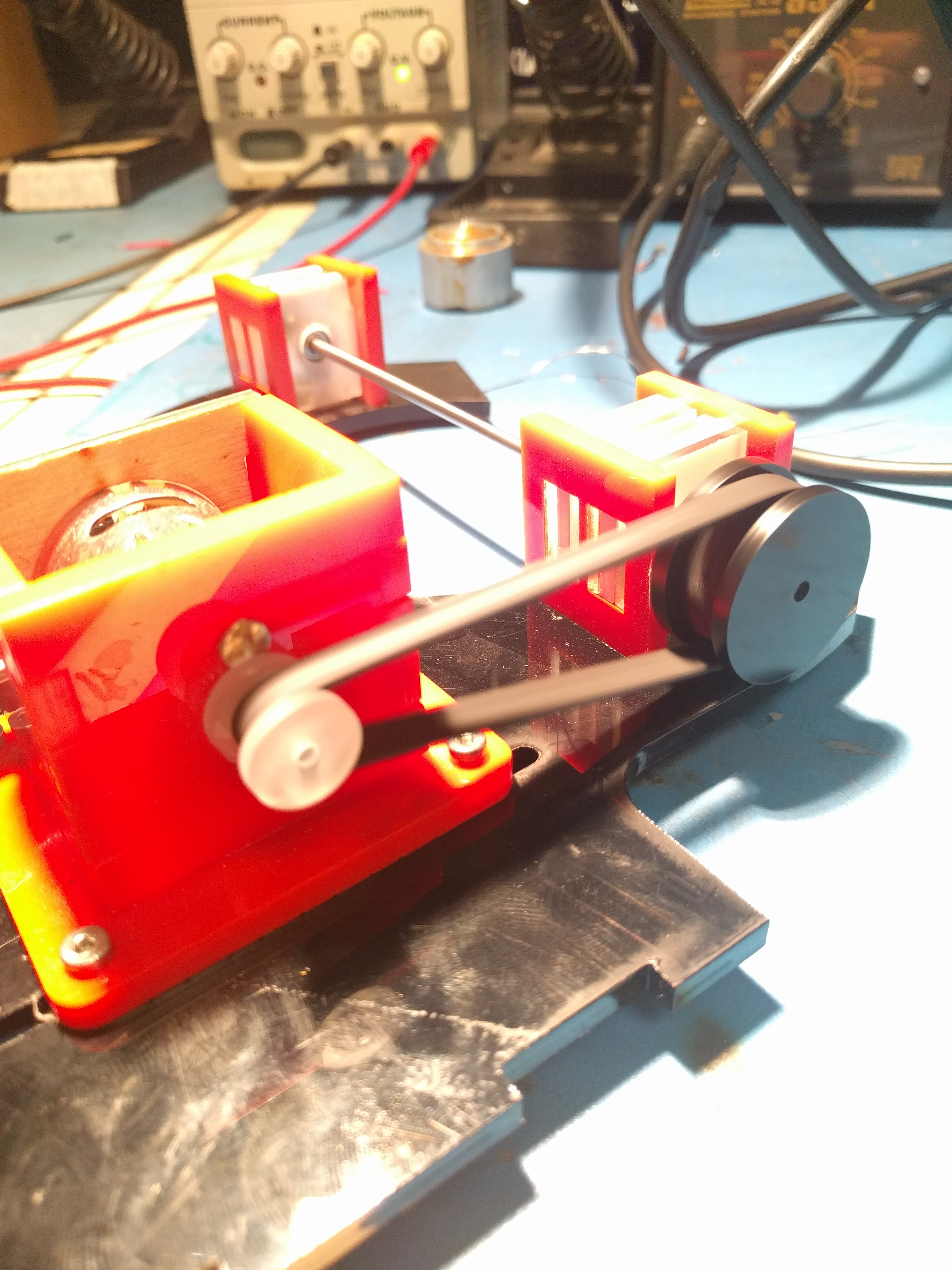
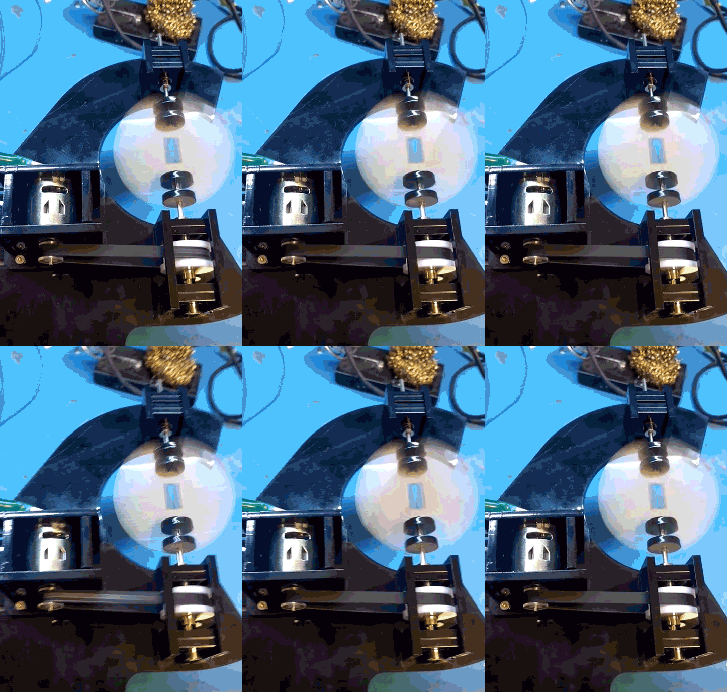
First of all, the system worked. Laser cut pulleys work great, I’ve used them before on other projects, and my tension and belt driven design seemed good.

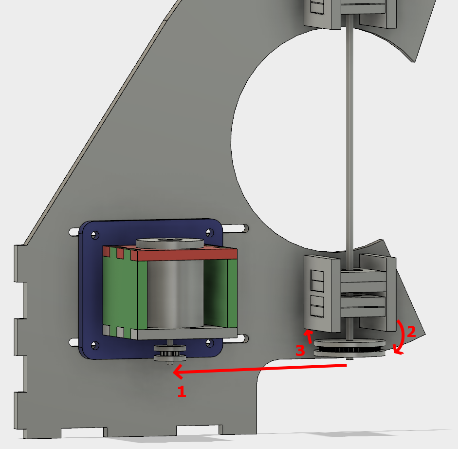
When that main shaft got split and attached to my PCB mock up, however, the shaft was no longer properly supported.

The belt put leftwards force on the shaft (1), causing it to cantilever in that direction (2), and then cause the pulley to rub against the bearing block (3).

I was hoping that the two bearings above the belt would fully constrain the system, but alas, there is too much flex in the shaft or slop in the cheap bearings, with not enough distance in between them.

So, version two. This time with a supported shaft on either side of the driven pulley. I was trying to avoid that because the design and assembly both get a little more complicated.

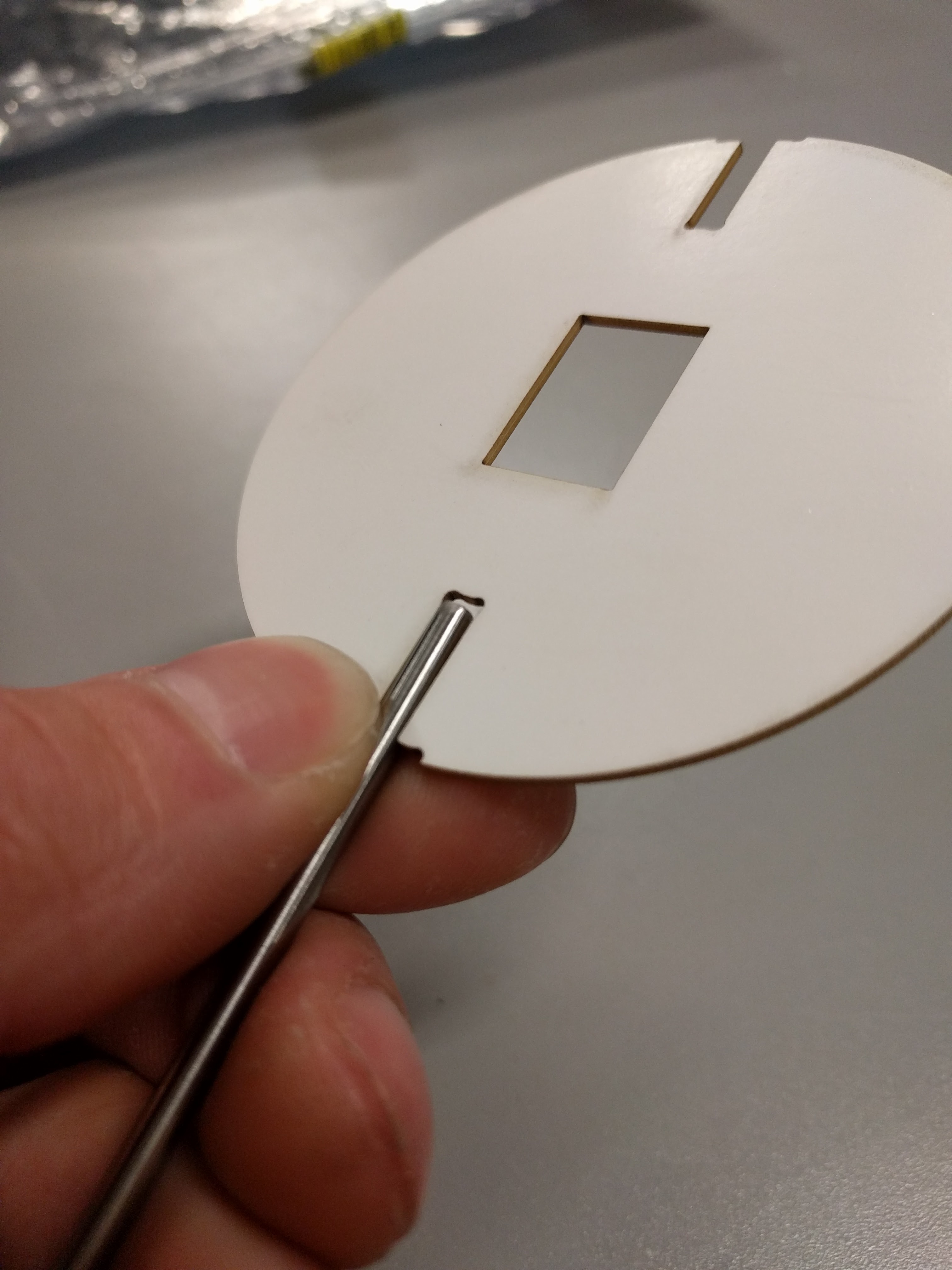
One more change was getting rid of the clevis pins. They rattled and I didn’t like them. Instead I swapped the smooth shafts out for D-profiled versions, and laser cut a notched circle to couple with the PCB.

After cutting and reassembly, it works great!

No more mechanical changes need to be made for this prototype to demonstrate that it works. Next section!

POV Globe – The Software

Persistence of Vision globes are a relatively simple project that everyone has to build, it seems. The fusion between mechanical, electrical, and firmware domains lead to some interesting challenges that are deceptively difficult to overcome.

It’s a great project with a low barrier-to-entry, but it’s also easy to put your own spin on it. Heh. Spin.

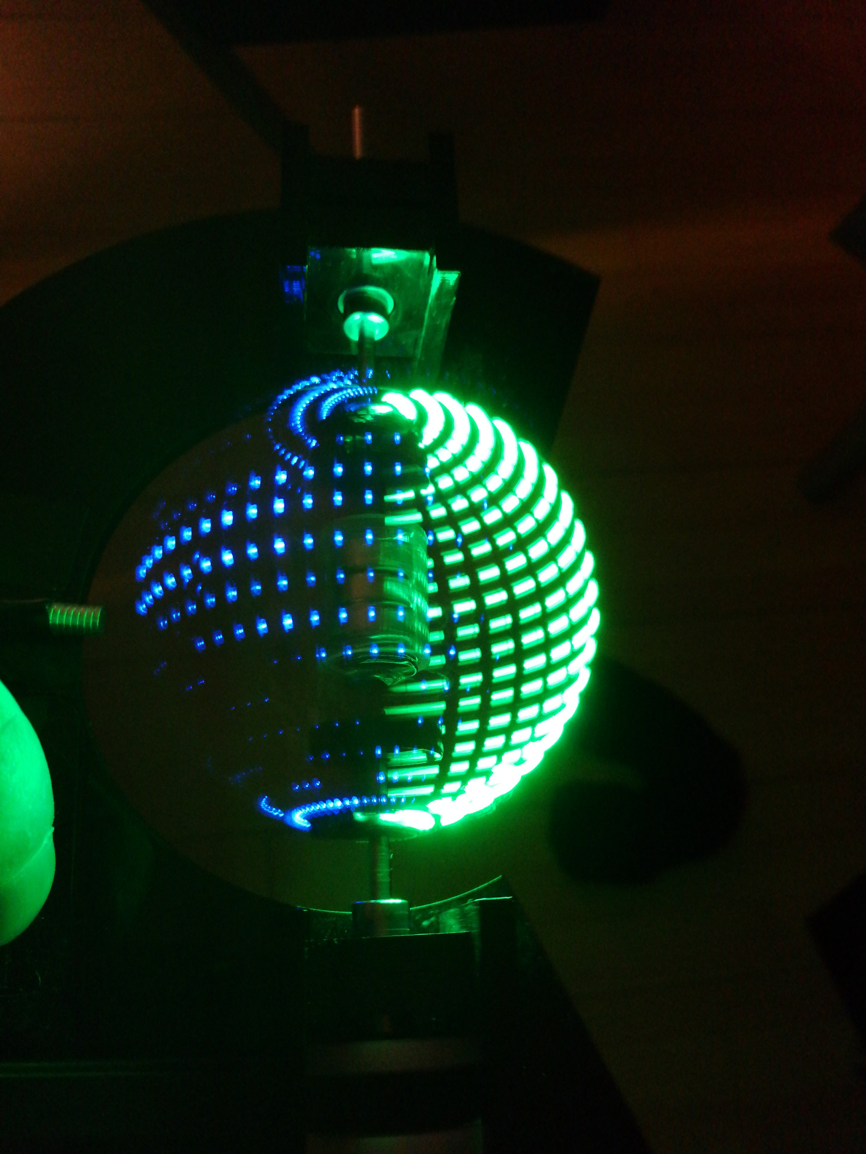
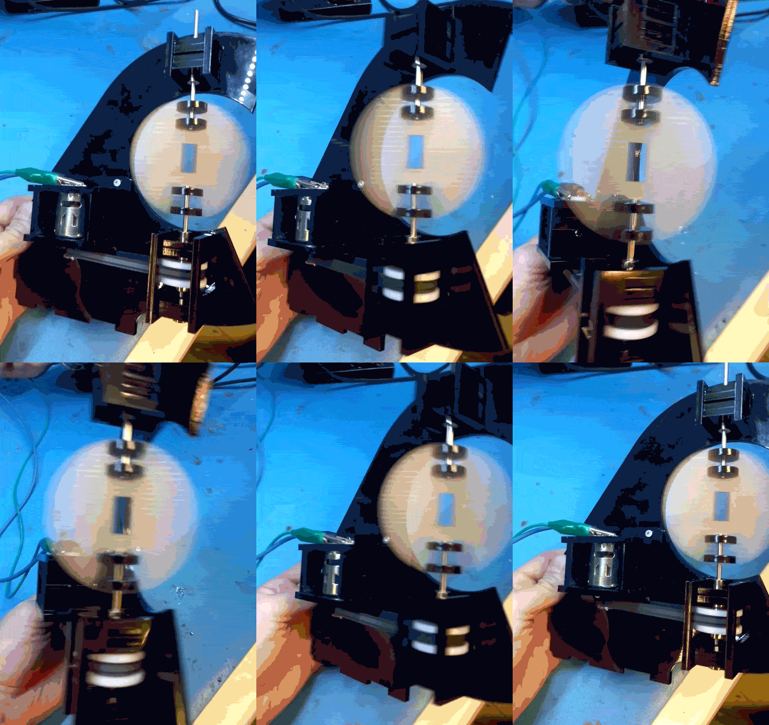
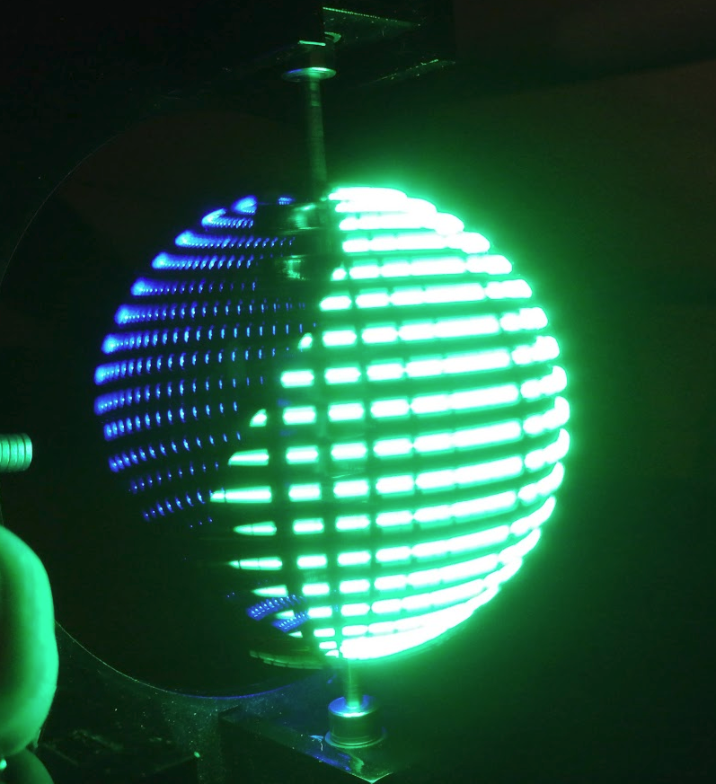
Teaser:

This post will only focus on the software (embedded and desktop), with other sections to follow.

Initially, the rough code flow for the PIC microcontroller for this was going to be:

  1. Rotate Hall Effect sensor past a magnet, sending a signal to…
  2. An input on the PIC, generating an interrupt
  3. Copy a timer’s internal value to a variable
  4. Clear the timer
  5. Divide the variable’s value by horizontal pixels to get transition times
  6. Set an interrupt at the next transition
  7. At interrupt, change the interrupt to trigger at the next transition
  8. Set data pointer to start of the vertical pixel data array
  9. Send out data at pointer via SPI to LED drivers
  10. Goto (7) until (1)

But that was before I discovered a new, amazing peripheral that some PICs have! Even the PIC16F1619 that I happened to be prototyping with.

It’s called the Angular Timer, and it’s pretty much designed for these applications.

The process is now:

  1. Set up AT with input, period, and and interval interrupt settings
  2. At period interrupt, set horizontal data pointer to zero
  3. At interval interrupt, send vertical line data at pointer via SPI to LED drivers
  4. Increment horizontal data pointer
  5. Wait

Substantially simpler, and much more responsive than polling and manually changing timers would be. The only thing that’s missing is a DMA peripheral, which only a few of the 8-bit PICs use.

This link to all of the files, code, firmware, mechanicals, and PCB are all on the Github repo.

In lieu of an elegant image update method for Revision 1, everything is hard coded into the firmware. The world map for the globe is stored as a set of arrays, and generated by a Python tool I wrote. In the tools folder of the above Github link, there is complete documentation. The gist of it is that you can pass it a PNG image, and it can process that image in a few different ways and spit out another PNG, CSV, or generated C files. Then simply include that C file in your firmware when programming the project.

uMesh

I’ve been working on an ESP32 module.

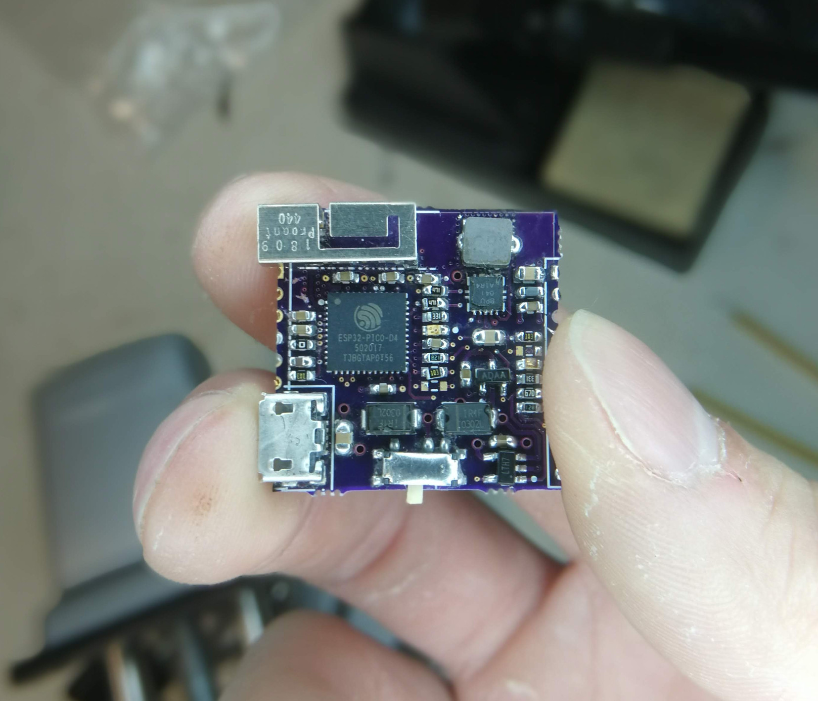
Part of the problem I’ve been seeing with inexpensive IoT dev boards, is that the design around the power system hasn’t been very good. Here’s my attempt to fix that. This is a battery-ready module with a proper lithium battery charge circuit, lithium battery protection circuit, power supply, and antenna, all in a 1 inch by 1 inch package.

The goal is to have a tiny, inexpensive module that can immediately accept a battery and be deployed in the field, along with 30 of its mates.

The battery/power circuitry is surprisingly complex, which is why the built-to-a-price-point applications often don’t have the “proper” battery control, opting instead for “good enough”.

And when I say tiny, I really do mean tiny.


The main interface to the world (other that WiFi or Bluetooth) are castellated headers on the left and right side. Those grant access to input voltage, battery voltage, output voltage, TX/RX pins, bootmode selection, and a few GPIO. Because of them, this module can be soldered directly down to a larger host board if necessary, and can even provide regulated 3.3V output to it if given battery power.

What sets this apart in terms of battery handling are a few things:

  • There is a buck-boost power supply to provide a constant 3.3V to the ESP32 through a battery’s entire range (3.0V-4.2V)
  • There is a cut off for battery when it hits 3.0V, to prevent over discharging it
  • When the module is plugged in (through castellations or through the USB connector), it will switch over to using that as a power source. It can be hot-swapped
  • Also while plugged in, there is circuitry for constant-current/constant-voltage charging of the battery
  • The battery will still charge while the device is switched off

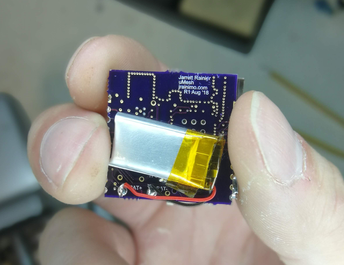
The battery just solders on to some pads on the back. Any size of single-cell will do, although the programmable charge speed relates to a resistor value that is soldered at manufacture time.


The USB port is for power/charging only, and has unconnected data pins. I also somewhat expect this microUSB port to shear off at some point, as they have kind of a history of doing that.

For the microcontroller, I’m using an ESP32-PICO-D4, driving a metal stamped antenna for 2.4GHz through a pi filter and 50 ohm impedance matched traces.

I haven’t really considered applications just yet, but it certainly does fill a niche for most IoT projects, given that a battery is usually necessary.

While waiting for shipping, and personal time to build it up by hand (mostly the latter though, Oshpark is awesome), I wrote an assembly and bring-up manual. It’s currently clocking in at 17 pages, but that includes a lot of reference. I’ve uploaded it as PDF here. That includes full schematics, part positioning information, net list, and BoM.

Here’s the Oshpark link to the project where it can be ordered (or gerbers downloaded too). It is a 4-layer board, and costs $10 for three.

Soon, I’ll write about programming it in an extremely sketchy way, programming it with the programming host board I designed, designing and tuning the antenna, and how to design it into a larger project.

LightBeam

In the deep, dark, depths of my project “to-do” list, I’ve always had a persistence-of-vision bicycle wheel light penciled in. I felt capable of doing it many years ago, and indeed, documenting the wiring was one of the driving forces for starting this website, but never got around to building one.

Eventually, products like the MonkeyLight came out, which did everything I wanted and more. Because “having the finished product” is rarely the goal of my projects, the very existence of a commercially available solution is sometimes enough to stop me from bothering.
For reference, the good version of MonkeyLight is $1000. Highway robbery! It is a great looking system, though.

But in August of 2017, I found a 32-LED bicycle spoke light on AliExpress. The cost at the time was $4.30.

Even now, it’s less than five dollars! That’s ridiculous! I can’t get individual components for that.
The only problem is that it displays preset patterns, and nothing more.

So I’m going to be upcycling! Get it?

And so I bought two.


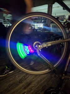
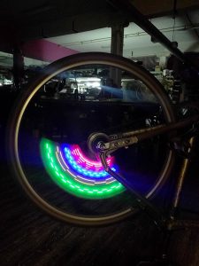
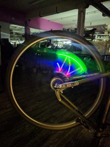
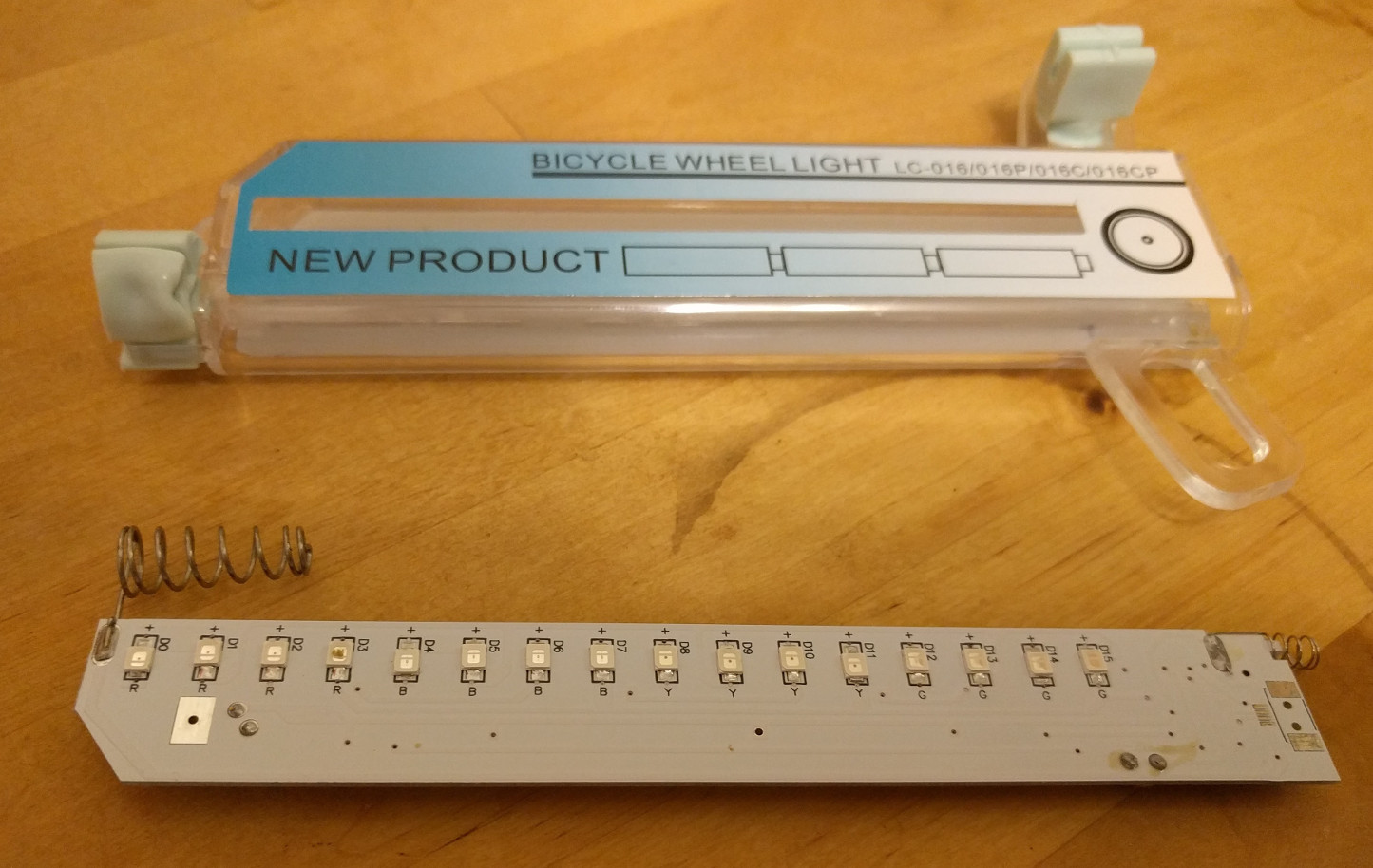
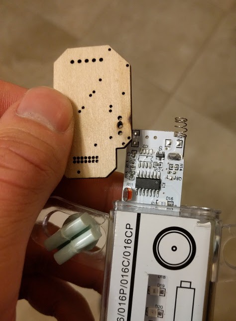
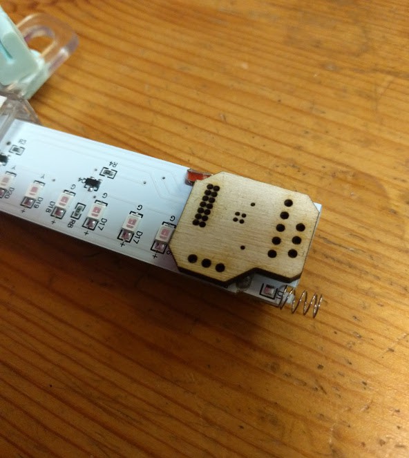
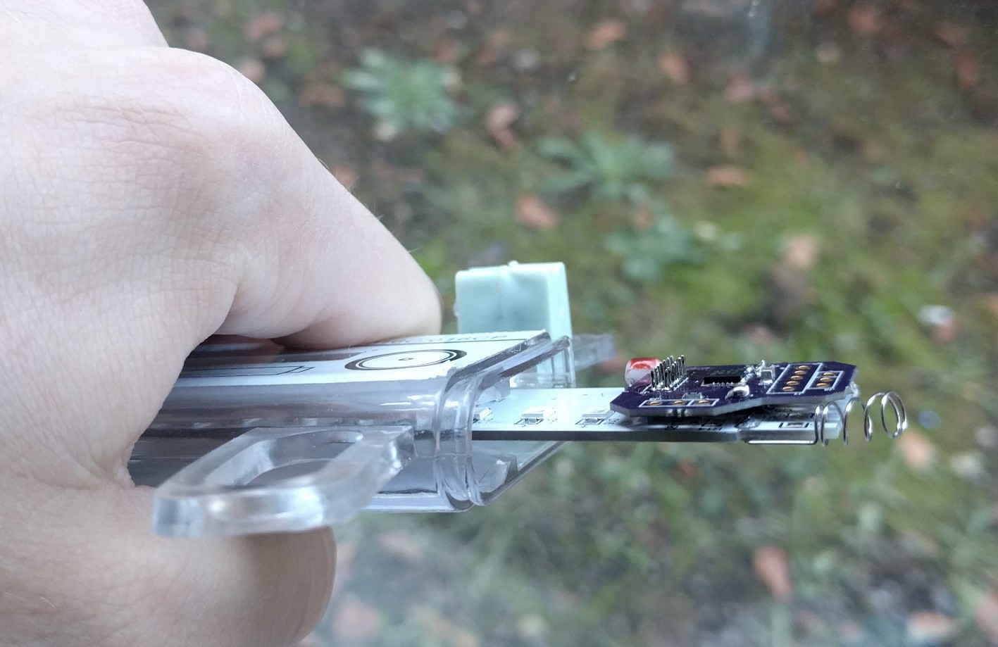
Here are a few terrible pictures of what they look like in action:


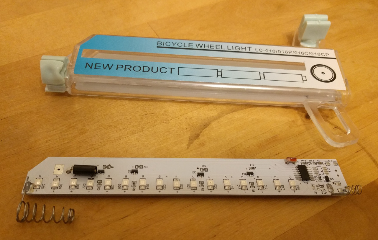
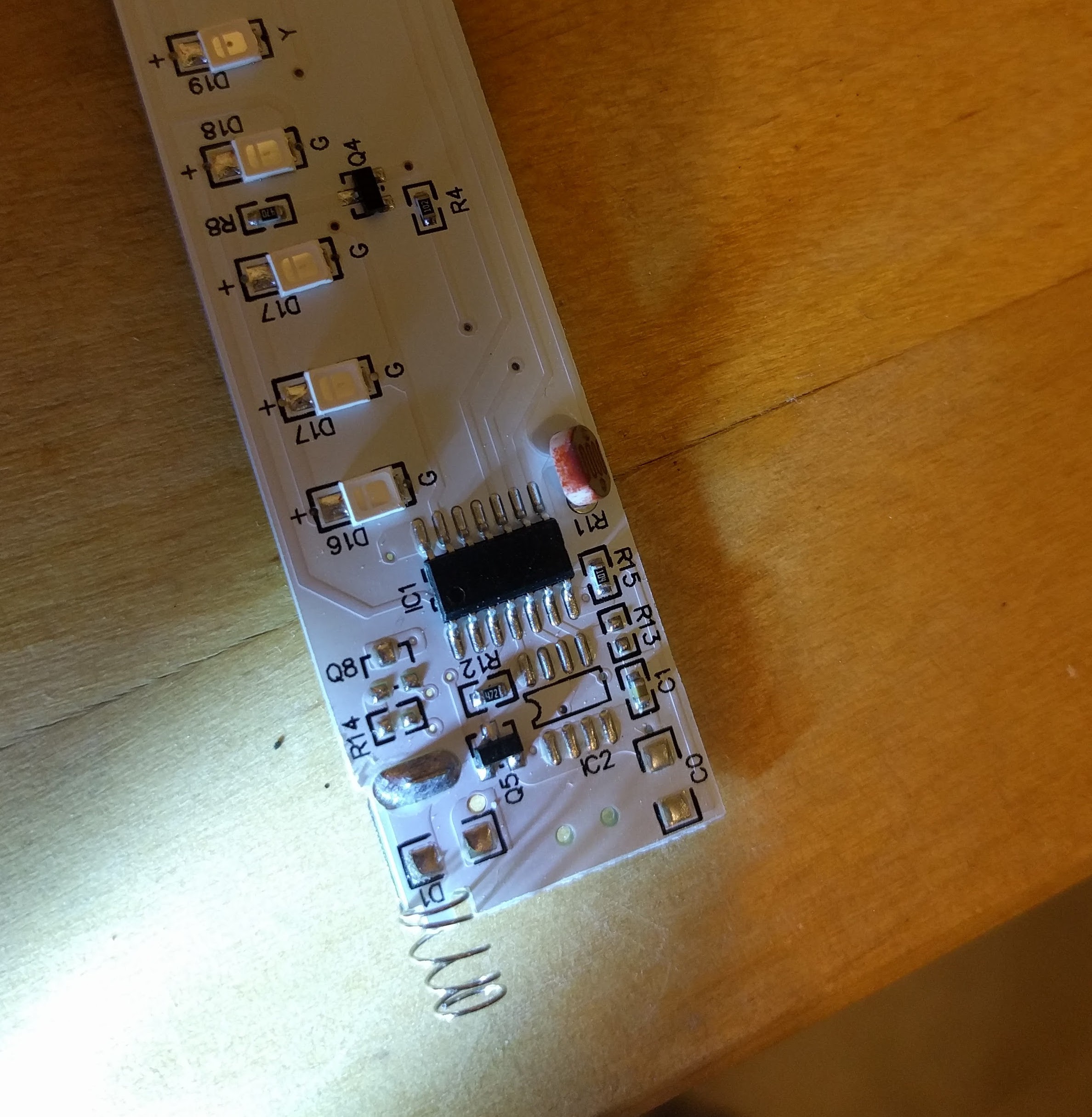
There’s the top and bottom. Fairly straightforward. Light-dependent resistor and vibration sensor feeding into a microcontroller.

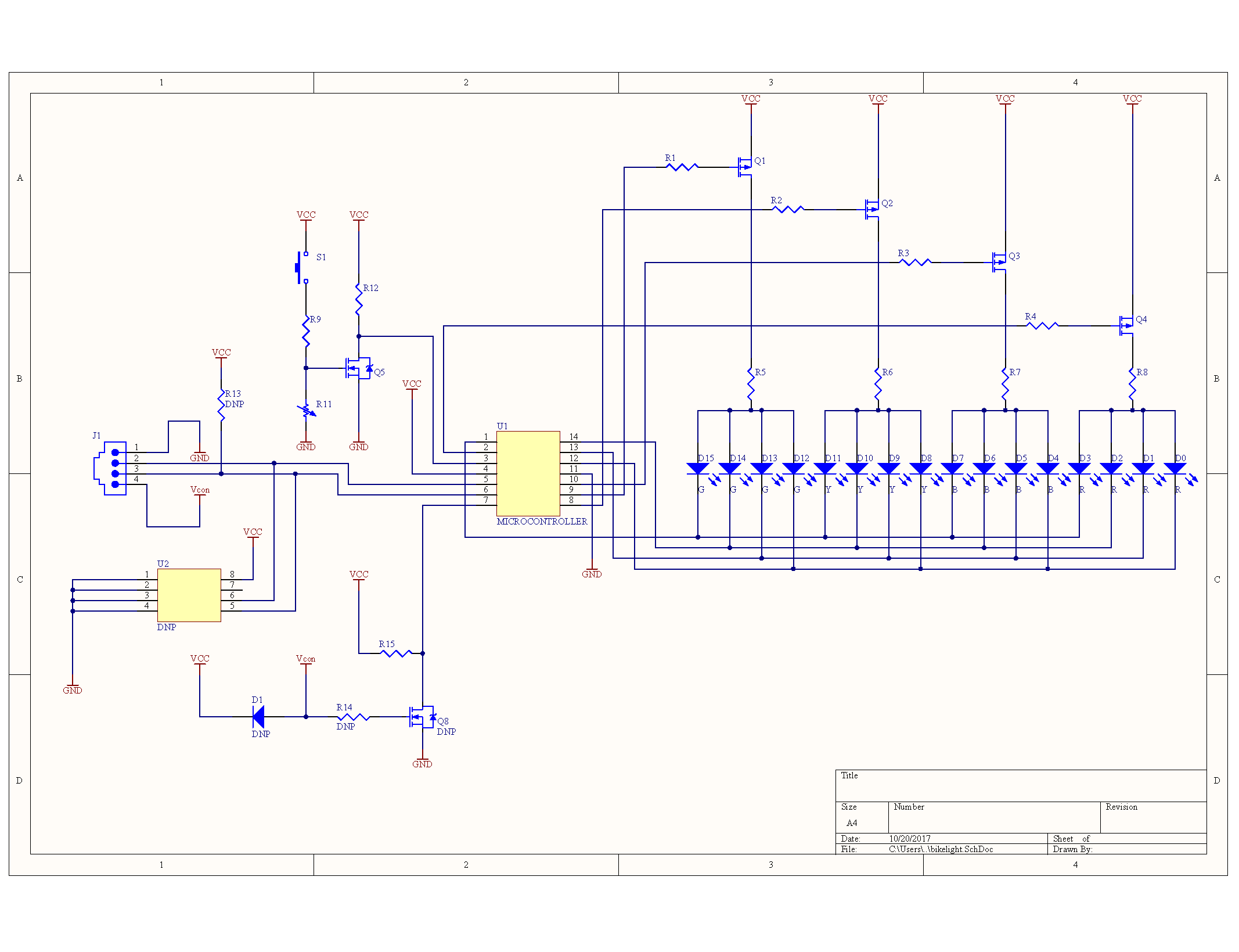
It’s super hard to photograph white soldermask in a way that displays the traces. A combination of that and buzzing pins out results in a schematic, like so:

U2 is probably (similar to) an AT24C02, an EEPROM chip, which isn’t populated in this PCB. Cost reduction on display! There’s an associated pull-up resistor and connector, also missing. Presumably there’s some model out there where you can plug in an I2C device and talk to the microcontroller, or add data to the flash chip.


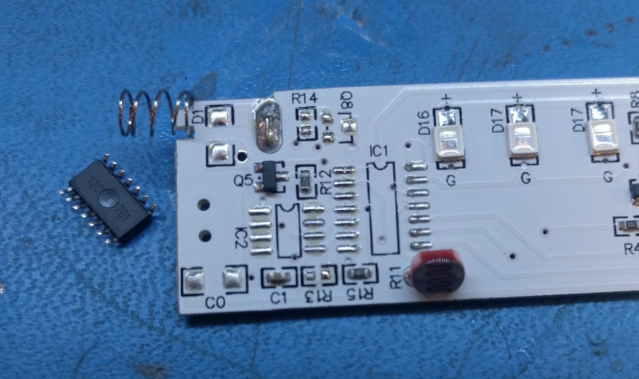
The other one is probably an EM78P153B, based on its pinout. Or very similar. Depending on the exact model, it’s either one-time-programmable memory, or masked ROM from the factory. Either way, there’s nothing I can do to its code. So, removal it is!

It’s interesting to see microcontrollers that rarely come out of China like this.


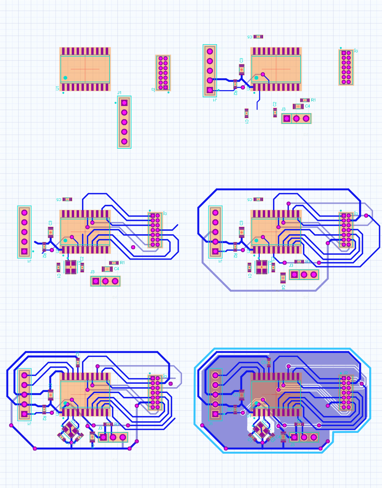
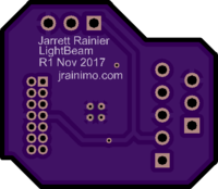
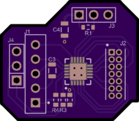
I have a pile of PIC18F14K50, so I threw the footprint onto a small board and headers that matched the 1.27mm pitch of the original microcontroller. I was using Upverter for this PCB, and it provides a pretty neat histogram:


After that, gotta see if it fits, using the convenient laser cutter on hand.


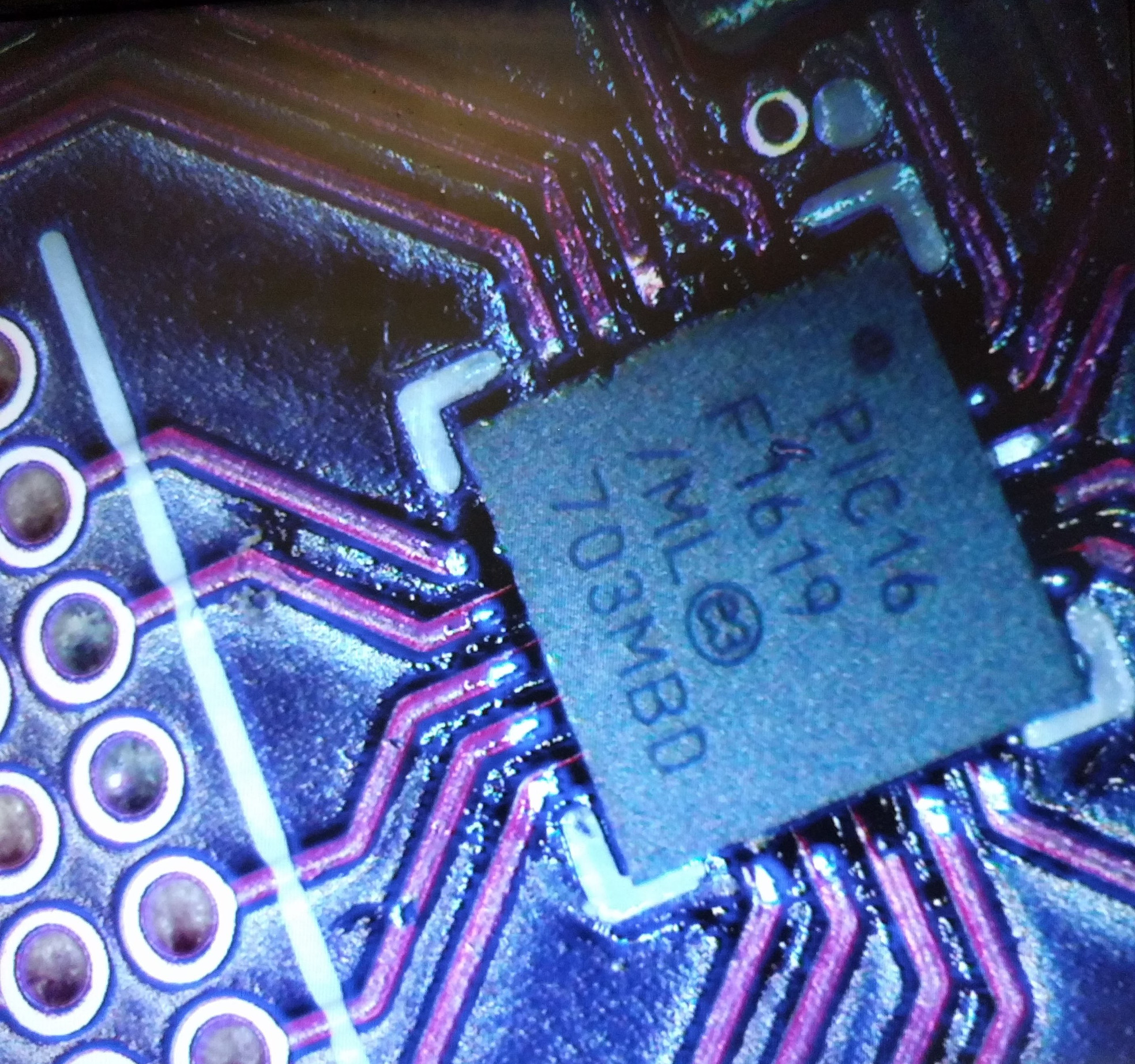
It most certainly does not! So the microcontroller was swapped with a smaller one, the PIC16F1619.


And it totally fits, so off to OSHPark it goes. You’ll notice how neatly the traces were able to be routed on this one. The PIC16F1619 is one of the newer PICs, and they all have something called Peripheral Port Select. Basically, any peripheral can be reconfigured to any pin. It’s pretty fantastic for simplifying board layout.


Receive boards, solder, inspect, looks good!


And then at the same time, remove old microcontroller…


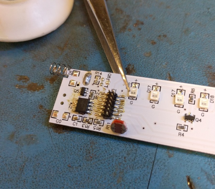
…add new flash chip and headers…

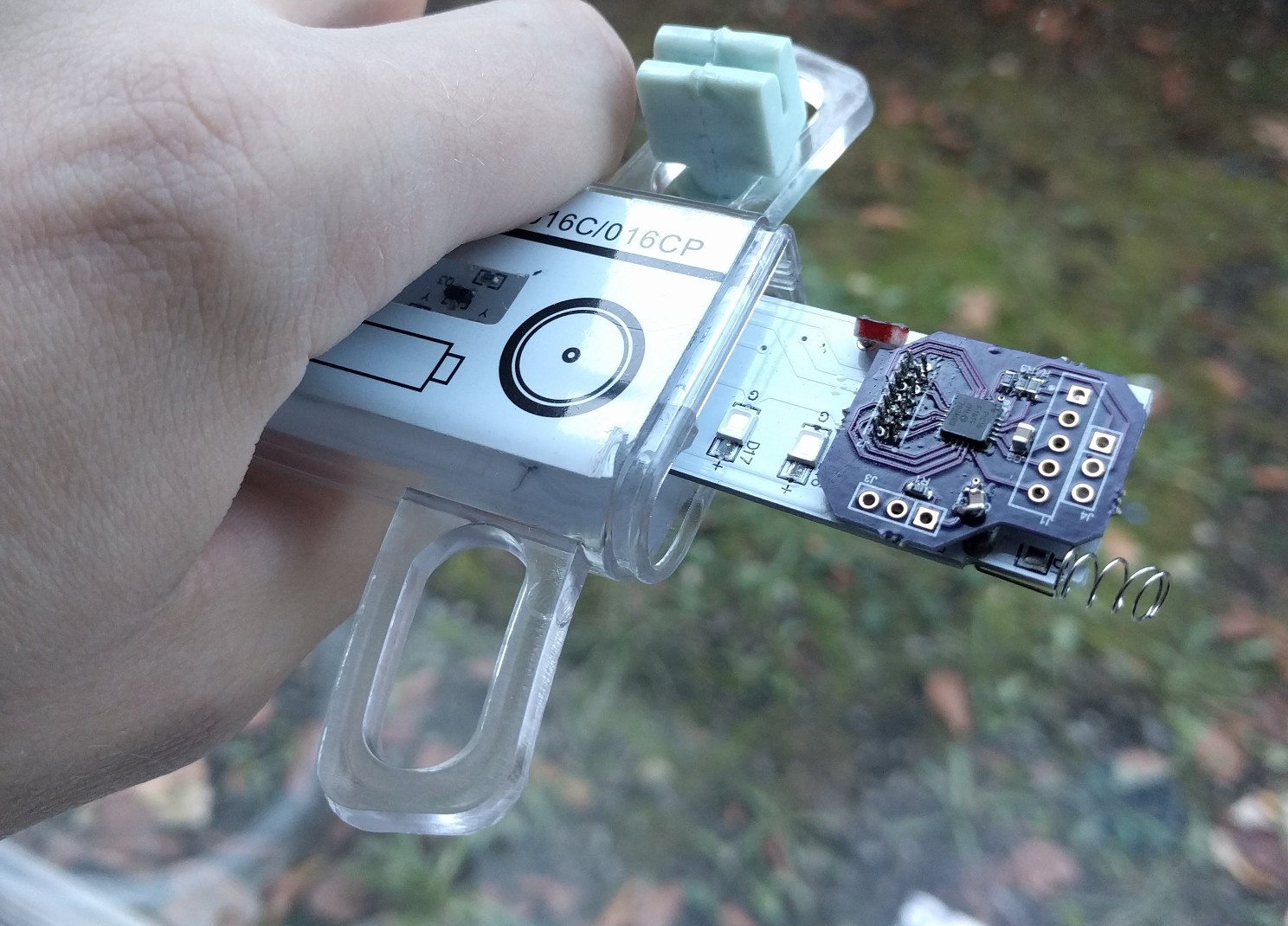
And then solder the whole thing down.


Feel free to fork/download/whatever the hardware files from Upverter, here. I’d be pretty stoked if someone else made some of these, too!

Another hardware update and software is coming in another post very soon. It’s a bit of a tangled web of interrupts, so I’d like to document it properly.

This PCB mostly worked, but the (optional) Hall effect sensor was bad and I changed it. And, final pictures of the result! That’s pretty important.

Infin1D, Rev 0.5

Before YouTube existed, I saw a video online. There was no spoken dialog, just subtitles in Japanese, with upbeat music in the background. It shows pictures of point-to-point soldering of a document scanner’s sensor and some sort of microcontroller. Then the single line sensor is put into a box (with a lense) and taken for an adventure.

I’d love to find this video again, but the main takeaways were that by reducing your camera to one dimension, you can fake the second dimension to create infinitely long images.

The creator of that original video set it up beside some train tracks, and got a long image of an entire train as it drove past the camera. Similarly, you could put it beside a road and get images of cars, or in the playa at Burning Man and capture the eccentric costumes as Burners ride past on bikes.


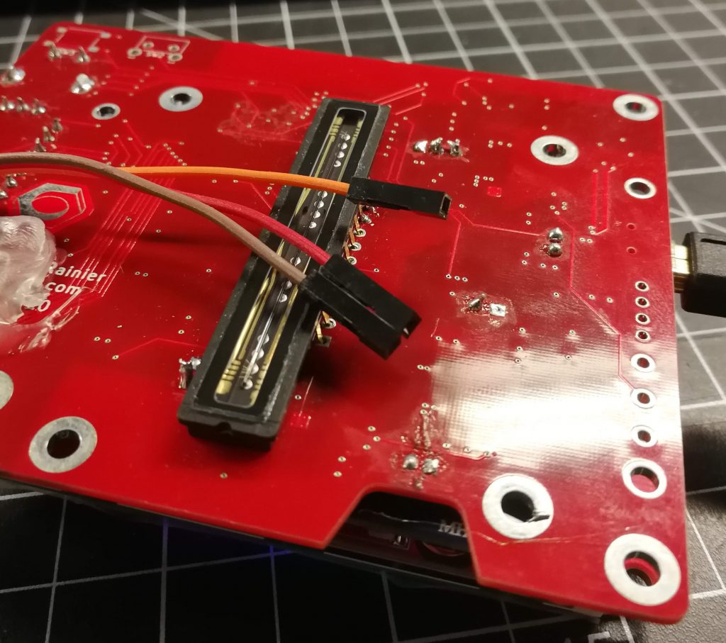
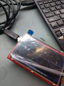
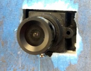
I wanted to build a quick test. Lurking in my parts bins, I have a single-line camera module, and a massive pile of old LCDs. For this, I selected an Arduino shield labelled MCUFRIEND 3.6″.

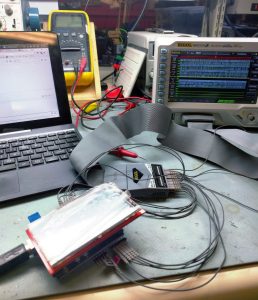
Searching around reveals that this model doesn’t actually seem to exist, but okay! The standard method of most Arduino LCD shield driving is to find example libraries that look like they have a reasonable chance of working, and then try them all until something does. I had to borrow an Arduino, because I’m not a huge fan, so I don’t even own one. How embarrassing.

In this case, the official-looking repository by prenticedavid is here, and GLUE_Demo_400x240 seemed to do a good job of driving this one. The code initialises it as 0x9327, which is the ILI9327 LCD driver. The datasheet for the ILI9327 is very good, so I may keep the LCD and write my own drivers for whatever non-Arduino architecture I eventually go with.

I did attempt to follow the maze of #defines in the Arduino library code, but I don’t recommend anyone do that if they value their sanity. I also put a logic analyser on it to grab just the output; this resulted similarly convoluted and unhelpful results.


While I’ll eventually be using a sensor designed for document scanners (lots more on that, stay tuned), the TSL1401 is a bespoke solution good for this test.


All-in-one sensor, lens, and brains that take logic level timing, and spits out analog values. 127 pixels tall, greyscale, and tiny, it’s objectively kind of bad, but fits the bill for now. I got it up and running in an hour or two.


Cool! That means I have a reference implementation. I’m not running this on an Arduino in the final version, but it got the job done in a quick-and-dirty way.

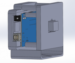
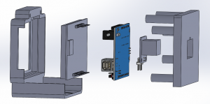
The whole thing was modeled up in SolidWorks, along with dimensionally accurate stand-ins for the electronics.


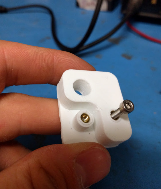
There are two 3D printer parts, adapted from the models of earlier jigs I’ve done, in keeping with the ethos of this test: quick and dirty.

I typically design around M3 screws, and used brass heat-set inserts to turn 3D printed cavities into threaded holes. As much as I dislike 3D printing, it has its uses.


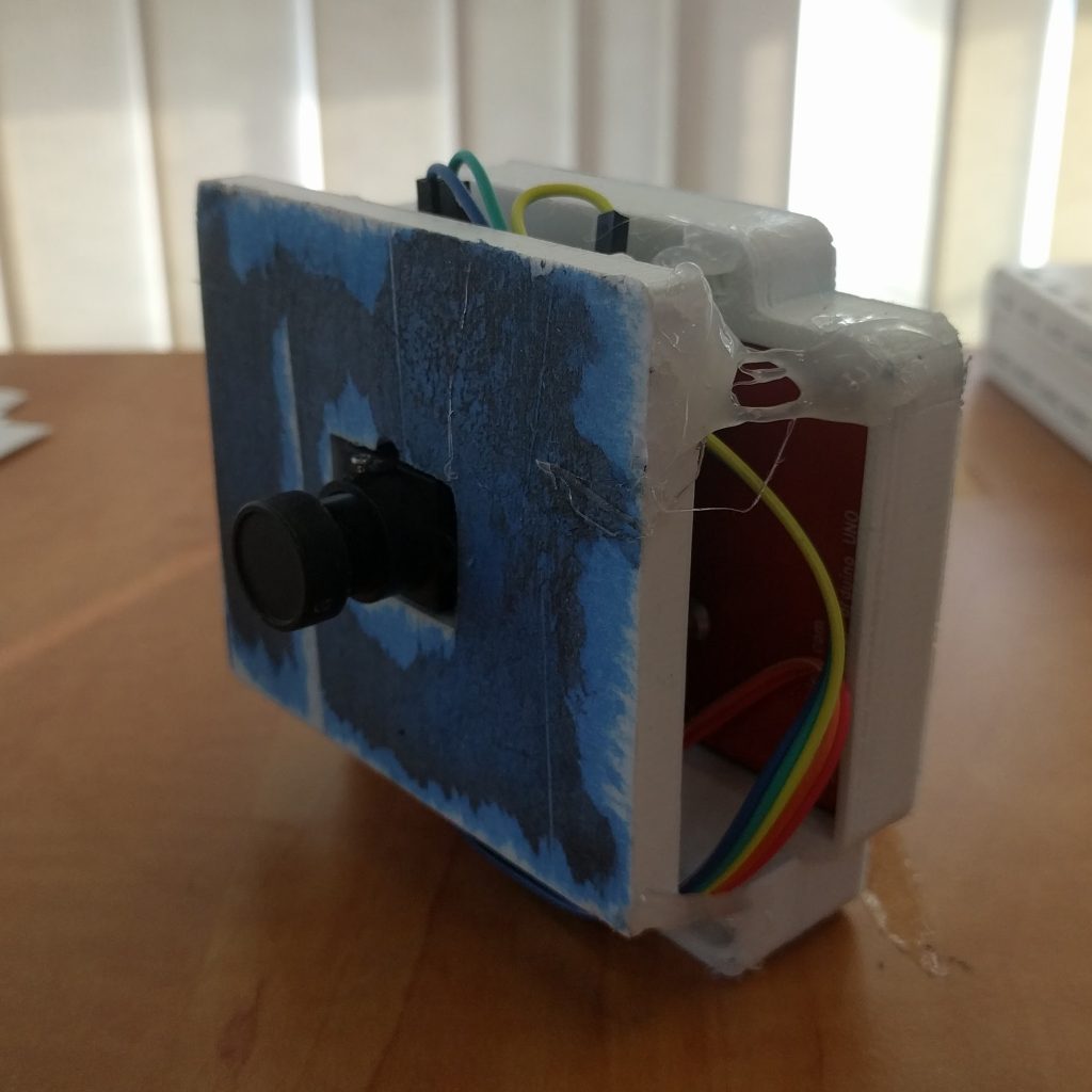
Both halves of the 3D printed enclosure failed while doing some of the top few layers, but the baseplates are there so nothing that can’t be fixed with some standoffs and hot glue.


The results from this test project, predictably, are pretty bad.

This is a handheld scan across my keyboard.


As a stepping off point, it’s served its purpose. Here is an incomplete list of changes that future prototypes will feature:

  • A better microcontroller. Probably an STM32F1 or STM32 F4 series. I like the flexible memory controller, which can be used to map virtual memory regions to LCD driver chips.
  • A better sensor. The current one is only 128 pixels tall, greyscale, poor quality, and relatively expensive for what you get.
  • UX – rotary encoders, buttons, LCD widgets:
    • Start/stop capture
    • Speed up/slow down scan/capture rate
    • Integration time adjustment
    • Post capture stretch/compress
    • Histogram
  • Saving to SD card
  • Battery power

Changing the sensor might not actually make it to the next rev, it’s a big project on its own. Sourcing a sensor through Taobao probably, figuring out how it works, driving it, building a board to work with it, and all the mechanical work of lens selection, mounting, and measuring.

Either way, I’m happy to leave this for now, and return to it when I have cleared out some of my project backlog.

Sugar Glider Wifi Throwies


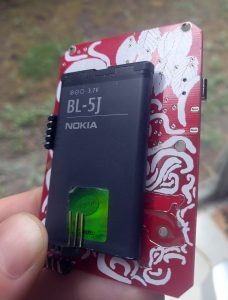
I have access to a big box of Nokia phone batteries. This is a problem. It is very large. I do not have enough Nokia phones to use them all.

There are three sizes:

BP-6MT (1050mAh), BL-5J (1320mAh), and BP-4L (1500mAh).

After some catalog-hunting (be vewwy vewwy quiet), I’ve found the connector they use, the A117827CT-ND.


Update: This handy website has sizes of various batteries listed.


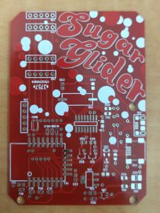
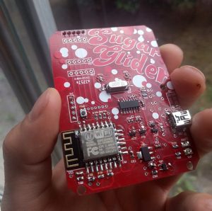
This PCB – I call it “Sugar Glider” – is a battery-powered ESP8266 wifi module. It supports charging a single LiPoly/Li-Ion battery over USB, running off the battery, or both while it’s plugged into your choice of MicroUSB or Mini USB connector.

Mostly using the reference design of the MCP73831 charger chip, and it powers an ESP8266. There is also a CH340G USB-serial chip for programming, so it basically acts like a NodeMCU.


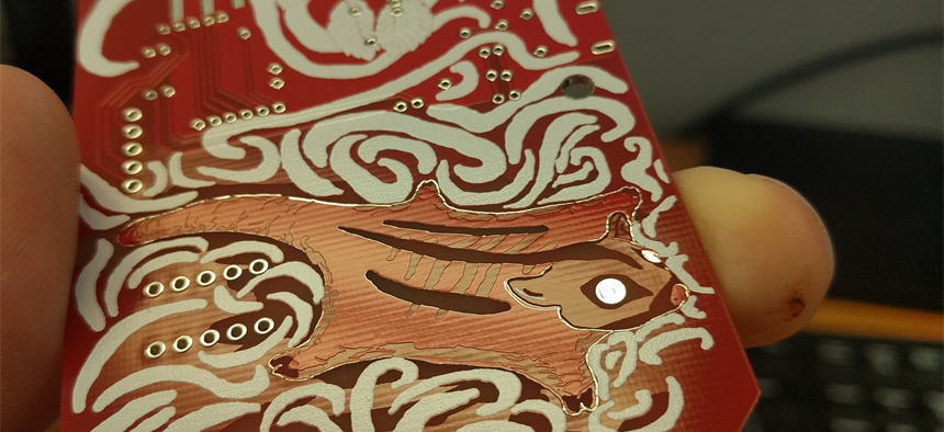
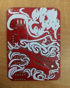
But wait, there’s more! Despite the simplicity of the design, and really not caring that much about it, it took a tonne of time. That’s because I’m rusty at drawing from not having done any in the last decade, and it looks like this!


This was done by exporting gerbers, converting each layer to B&W images, then loading them up in my (also decade old) copy of Photoshop. They were coloured according to my sampled colour palette, and then drawing commenced.

When I was done, they were loaded back into CircuitMaker using the techniques detailed here and here. I think I’ll try to do more of this in the future. Having this much unused PCB space is rare, though – It was needed to act as a sled for the batteries, so it’s quite large. Usually I make boards as small as reasonably possible to save on costs.


The assembly went reasonably smoothly. You have a choice of populating the micro- or mini-USB connections. I prefer the mini, because there are something like 20 different possible microUSB connector footprints. In future versions, I’ll probably also use a 0-ohm resistor to select which one. Having an unpopulated connector on the same line is a recipe for bad signal integrity and unwanted antennas.

The power supply portion of this is simply a low-drop out (LDO) linear regulator, because I wanted to bang this circuit out quickly without having to design a switch-mode power supply (or: the Right way to do this project). Slight problem: the LDOs I sourced from China, well, weren’t very LDO. They had a full volt drop across them, leading to 2.7v seen on the ESP8266 at nominal battery voltage. No bueno.


The solution is very simple; just replace the regulator with a proper part from Digikey, that comes with a datasheet. Modern ones are usually closer to 0.2v. That’s the stuff.

This project was created in CircuitMaker. Here’s a link the cloud project page, but here is a zip file of all the relevant files – Schematics, PCBs, gerbers, and layer drawings. The resource-heavy images don’t play nicely with PCB design, so I recommend deleting them while editing the PCB, and then adding them back in right before export.

Cosmetic Surgery on Altium Boards

I’ve been a really big fan of PCBModE for a long time. Designing beautiful PCBs is a seriously difficult skill, and a serious abuse of the PCB board houses. Saar Drimer of Boldport has done a great job, and anyone reading this should definitely check out his stuff.


Where it falls down, though, is doing complicated and electrically correct circuits – No DRC/ERC rules, and not even a schematic view. I use Altium for my main PCB package, but it’s pretty tricky in it to get images into the PCB. It is possible, if a little convoluted, so here is my method.


Part of the problem is that I’m using Altium Designer 10 – Newer versions are better with this, it seems.


This process uses the CreateRegionsFromBitmap script. On my machine, it’s located in:

C:\Users\Public\Documents\Altium\AD 10\Examples\Scripts\Delphiscript Scripts\PCB\CreateRegionsFromBitmap

It’s also broken and required a couple fixes.

When I opened up PCBLogoCreator.PRJSCR in Altium and compiled/ran it, I got an error, missing semicolon at this line:

GrayWidth := Round((1 - sqrt(GrayProportion)) * PixelToCoordScale / 2);


Instead of trying to fix it (I don’t got time for that), it was replaced with:

GrayWidth :=0;


Second error was a missing function. This was fixed by copying LayerComboBox.pas from the PCB Logo Creator script into the working CreateRegionsFromBitmap script directory and project tree.

Then hit Run, and a dialog box pops up!


My workflow here was to identify what different shades I could get on the PCB, and the best ones for my image.


Here is a list of portions that contain wildly different shades:

  • Bare FR4
  • Copper
  • Soldermask
  • Soldermask with copper underneath
  • Silkscreen


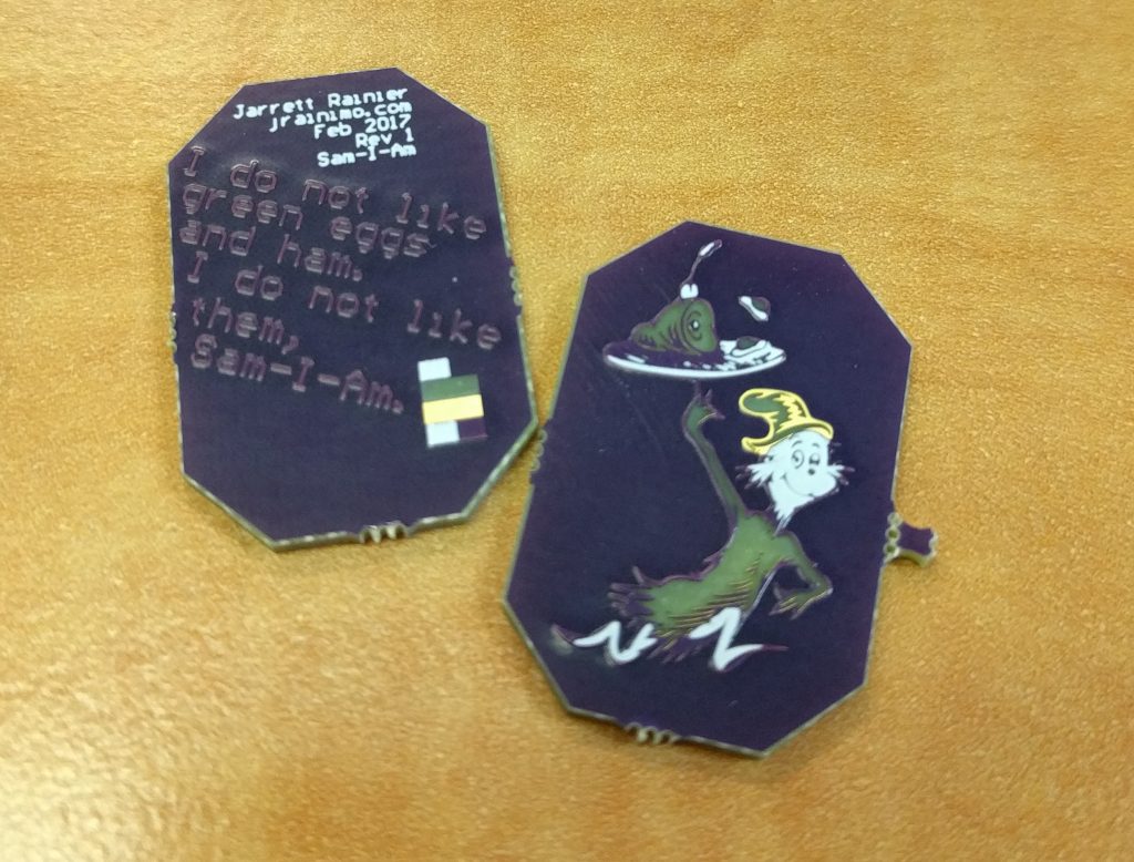
Predictably, that means that images with 5 or fewer colours (including backgrounds and outlines!) work best. For a non-commercial practice piece, Dr Seuss was the clear choice.

First step is to pull the desired image into Inkscape and separate all the component colours.

The way Inkscape handles colours masking each other – like the yellow layer being the “background” and relying on it being blocked by the colours on higher layers – doesn’t really mesh with the way they show up on PCBs. After some fudging around (as quickly as possible), this is what I came up with.


And here’s how the PCB turned out in OSHPark Purple.


The thing is super small, so you can see how the soldermask pools up against the raised copper and causes weird bubbles.

I didn’t spend a huge amount of time trying to fit the best colour scheme to the image. But what I’ve done since then is scanned a few PCBs that I have kicking around, and created this handy palette for a various soldermasks!

The best method for using these is probably to ignore the PCB aspect entirely at first, and draw a pretty picture in your illustration application of choice, using just those colours. Translating that to PCB is the secondary concern, and much easier. Something to note is that the “copper” colour of the DirtyPCBs palettes is HASL tin grey on top, and the OSHPark scheme is ENIG gold on top. Both of those are shiny.

Another technique worth trying is crosshatching. That might work out really well, in the same way that it works for laser cutting.

Sure, we’re brute-forcing, but what’s the rush?

Ironically, in the process of writing a really fast implementation of the WPA2 encryption scheme, it was necessary (or at least easier) to first write a really slow implementation.

Here is my wpa2slow Python module.

To be fair, the actual speed at which this hashes isn’t the point. The point is that I have an entirely native Python implementation of how the entire WPA2 algorithm works, with an emphasis on code being clean, easy to read, and forgoing any speed optimisations that hinder legibility. Judging from the quantity of misinformation I’ve seen while researching this topic, someone will find this project useful. A lot of people have been having trouble trying to fit all the pieces together, over the years.

At first, I included the pieces as mock objects for unit testing. Each of the pieces (SHA1, HMAC, PBKDF2, etc) were built up over a period of several months, vaguely mimicking the interface format of equivalent existing hashlib libraries. Unfortunately, all of the standard Python hash libraries are really inconsistent!

For example, to hash a string with SHA1, I’d use:

output = hashlib.sha1(str)

Makes sense. But to then hash it with HMAC-SHA1, I’d do:

output = hmac.new(secret, value, hashlib.sha1)

Which is pretty weird, in this context. It makes more sense when you realise that HMAC can work with multiple sub-algorithms (commonly SHA1 or MD5), and you can go multiple rounds with adding more salt. That’s not the case in my implementation, however, so copying the format was a mistake.

One thing that rests solely on my shoulders is the massive amount of debugging information, hacky fixes, and generally poor code I’d written while focusing on an entirely different problem.

If I had written it cleanly from the beginning, it would have been a lot less work, that was silly of me.


Anyway. It’s pretty decent now. Check it out, read the docs, or install it!

pip install wpa2slow

ReacTick R1.5

Prototyping aw yeah.


After the first version of my LCD widgets, there were some things that I was planning on changing for the next respin. R1 just to get some hardware in my hands and start writing code. This next one is all about the cleanup.


The last version of R1 is here on GitHub. It works… Poorly. The code in the test folder is stuff to help me prototype, before I got to a working model. Originally, I tried writing an LCD driver in Python for the Raspberry Pi GPIO, but the output seemed super unreliable. Instead of taking the time to troubleshoot why, it was faster to port that code onto a PIC dev board, which worked great.

Once I had a known-good LCD (using the shift register), I finished soldering up the rest of the board and tried to bring up the whole board. It never quite worked properly, and here’s why!

When I was first drawing my schematic, the most common ESP8266 module was the ESP-12. Right around that time, November of 2015, the ESP-12E had just come out, with a bunch of extra pins. No one knew much about this at the time, but the conventional wisdom suggested that it was safe to include them in my design, allowing me to get away without using an additional microcontroller. Turns out these extra pins are associated with the flash memory, and using them willy nilly causes strange reset issues. Guess what kept happening when I was trying to test my fully populated board?

So before a complete rethink was in the cards, here was the original plan for revision 2:

  • The LCD has two little mounting tabs on the sides. An appropriately sized via to accommodate them will make the LCD fit better and prevent wobble
  • One of those mounting holes will interfere with the switches. Move them somewhere else. Specifically on one of the short edges, because the current location causes damage to the LCD when the buttons are pressed while the screen is face down on a table
  • Silkscreen for momentary switches to include functions (RST / PROG)
  • Add in the clever circuit that the NodeMCU group uses to enable button-less programming
  • Remove all unnecessary resistors:
    • R7 connected to LCD_RST
    • R10 connected to LCD_RS
  • Change LEDs to 0805 or something similar. I’m using 3528s, and they are huge and super bright and look out-of-place
  • Change user-settable LED to connect to a pin that is not GPIO16. Apparently some manufacturers (not mine) connect it internally to the ESP8266 reset pin
  • Change all the SIPO shift register pins from bit-banging to use the ESP serial ports – Should be faster, and allows me to…
  • Change requirements from an ESP-12E module to just and ESP-12, which has fewer pins
  • Break out extra ESP pins to some unpopulated pads for future hacking
  • Break out LCD touchscreen pins for future hacking
  • Add more testpoints for debugging (and future hacking)
  • Big decoupling cap


Some of these ended up making it in, but the new system design deprecated other points. So what’s new in R2? Stay tuned to find out!

R2 Paper