Archive for Jarrett

I Made An IoT

I haven’t actually made an Internet of Things, thing, before now.

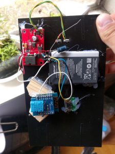
This is mostly just to throw some stuff together that I already had lying around. I’ve got a DHT11 temperature/humidity sensor, a WeMos D1 Mini ESP8266 dev board, a switch-mode power supply module, and a solar panel.

I turned it into an investigation on solar charging and ESP8266 power modes, while spending As Little Time As Humanly Possible on cleanliness, quality, or polish.

Yeah, this is super simple, and equally janky.

Threw it together in an hour with liberal amounts of hot glue.

Predictably, the solar panel was never able to supply enough juice to handle the startup current of the ESP8266, and it never sent any data points.

So phase 2 was to add a maximum power point tracker (MPPT) module feeding a Nokia battery as a reservoir.

This one worked! It lasted about 18 hours until it died.

I’m sending data to Adafruit’s free(ish) MQTT platform, also for the same spend-as-little-time-possible reasons that this projectlet follows.

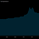
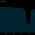
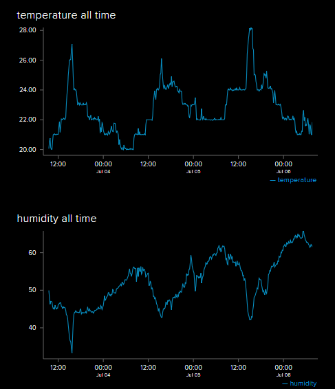
That spike/drop in temp/humidity is exactly the time period where I get direct sunlight in that window in May, so that’s neat.

Uptime is recorded in tens of seconds.

Now there are three problems left with this system:

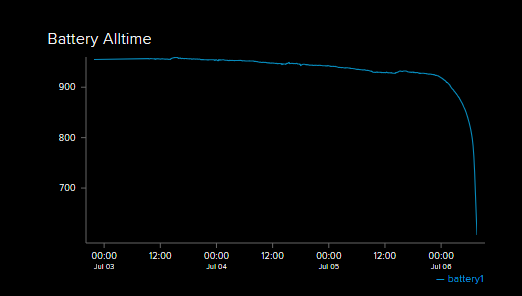
There’s no way to get an idea of battery charge until it dies.

The switch-mode power supply is a buck converter only, so as soon as the battery voltage goes below 3.3v (or maybe even above that), the output voltage cuts off, or possibly sags. I haven’t read the datasheet on this, so I don’t know or particularly care in this case.

Ideally, the solar panel can keep on top of the power usage. It doesn’t currently do this, partially because it’s sending too many datapoints (temperature does not swing wildly enough to justify once every ten seconds), and because I did not use proper deepsleep in my code. It’s just a while() loop that keeps the microcontroller chugging away at full bore.

So here’s the next update.

The ESP8266 has an ADC, but it’s limited to 1V max. With a max Lithium Ion voltage of 4.2V, I used a voltage divider of 1k in series with 4.7k and 10k in parallel. And then I realised that there was a built-in 220k/100k voltage divider designed for ~3.3v max, so I swapped mine out for a series resistor get into the 4.2v ballpark. This is all very approximate and I only had 680k resistors on hand, so 7 in parallel got me to 97k.

From my Switch Mode Tale, I happen to have a SMPS kicking around that is perfectly suited to the voltage ranges of the battery, too, so that goes in.

And, finally, the code changes were trivial. Another data point (battery) was added, and naive delay loops were changed to proper deep sleeps. This also required tying pin 16 to RST.

Still curious about battery lifetime, I commented the deep sleep mode out while running another test. This is still a while loop:

It lasted three days, and you can clearly see the spikes in temperature for a few hours in the afternoon as the sun hits the panel directly. And look at that lithium battery discharge curve!

I haven’t looked into my MPPT in detail, but that would likely be one of my next targets for investigation. I know it charges the batteries because I left it to do that for a few weeks in between tests, and the batteries were fully topped up each time. But I suspect it charges them really slowly, based on the lack of noticeable bump on the graph during sunny periods.

At this point, I took a brief hiatus from this side-project to do Important Things, and then it became autumn.

Using this power usage analysis, eventually, I will chip away at some of the possible optimisations. Some of the considerations described by Erik are obvious, but some of the others are quite clever. A mental shift to paying attention to the order in peripheral bring-up in a WiFi device is fun, and not something I’ve had to do much before. I will come back to this, for sure. Likely when I finish Rev 2 of my Sugar Glider board. As it stands, this side-project is in danger of going over my allotted five hours of actual build-time.


PCBs of Unusual Style

Shallow


As a test, I designed a nautilus-themed PCB in PCBmodE.


PCBmodE is not your standard ECAD package. It’s a collection of JSON files that get converted into SVG or gerber files.

There are some limited tools to convert SVG files back into JSON, too. It can be thought of as forward- and back-annotation.

There’s no schematic editor. There’s no traditional PCB editor. The only interface is Inkscape itself. (Inkscape is an open-source vector software, like Adobe Illustrator)

The end takeaway is that these circuits are drawn, not engineered.


The whole repo is here. All of the JSON files are the source files, which can then be compiled into SVG (for viewing and some minor edits), or to gerber (for manufacturing).


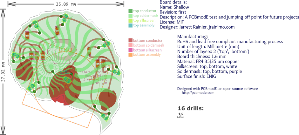
The OSHPark gerber viewer says it’ll look like this:


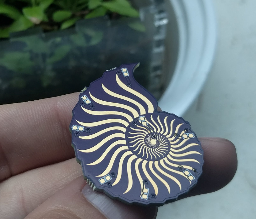
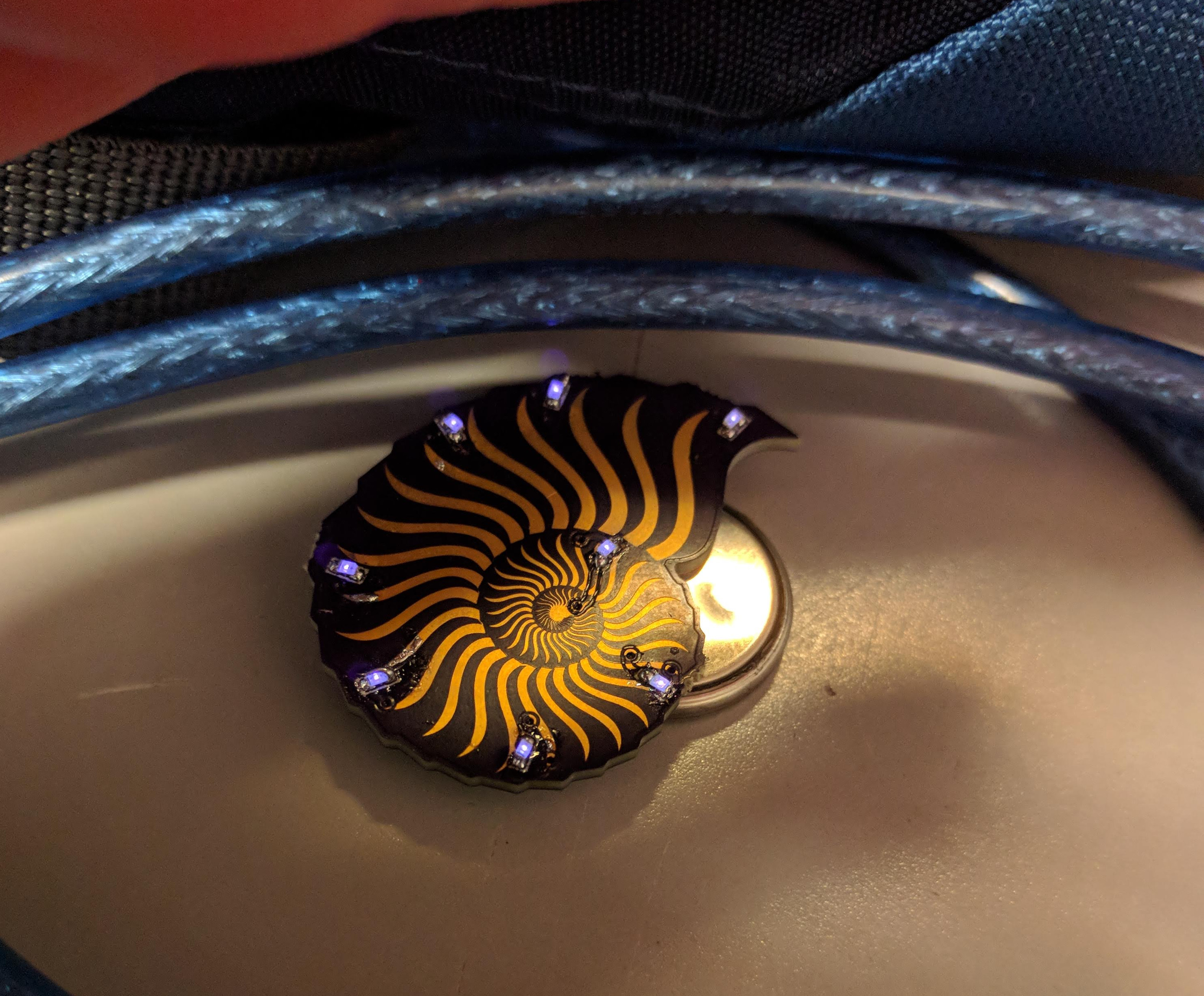
And here is the final board:


It’s surprisingly difficult to photograph purple LEDs. It was suggested to me that they may have strong UV components that are overexposing that part of the image, so they usually show up as white or very light blue.


Rest assured, they are way more pleasing to the eye in person.


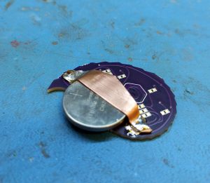
It’s interesting to note that the battery holder footprint was a Boldport component (it looks like a ladybug!). It’s designed for one of those cheap stamped metal CR2032 battery holders, but I don’t have any. It was easier/faster for me to grab some sheet copper and cut out a holder with tin snips.


The workflow of PCBmodE is a little bit jarring for someone expecting a standard PCB tool. It’s all laid out in the official docs, but I didn’t believe it until I tried it. Editing JSON files is almost the only way to interact with the software. You edit, compile, and view it in Inkscape. Some very small amount of things – Component position and traces, mainly – can be extracted back into JSON, but that’s it.

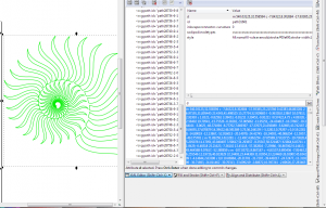
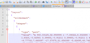
Even for outlines, the best method is to draw them in Inkscape, then copy the SVG paths and then paste them into the appropriate JSON:

For moving components around, there are a lot of SVG layers present for each component, but the extract command only seems to care about the origin. That little dot in the middle:


Three last things:

There’s also no “generate new board” command. Official recommended procedure is to fork one of the existing boards and modify. The docs are outdated, the sample is for an old version of PCBmodE that won’t work. I like BINCO for something really simple, or The Lady for something that uses every trick in the book.

Don’t use the official repo. This fork(as of June 2018) is the almost-official dev branch that has a lot of improvements (including Python 3!), and presumably will be merged back into mainline at some point. This command will install the proper one:

pip install git+https://github.com/threebytesfull/pcbmode.git@improve-test-coverage


And, finally, there is one issue that will prevent manufacturable gerbers. I described it here.


The next step

So, obviously this software requires some fussing, initially. It’s pretty nice once you have it set up, though. No issues, as long as you know what they are ahead of time.

What’s still a pain for daily use, however, is building usable circuits. Lacking a schematic and having to hand-draw traces as vector paths is painful.

So I quickly grabbed the first complete PCB available in Upverter, my LightBeam board. And then I wrote a conversion tool.

Here it is in Upverter:


And then in PCBmodE:

Workflow is now: Make a PCB in Upverter (or import it from something else!), Export as OpenJSON, convert it with my tool, then edit the PCBmodE JSON files as required to prettify them up, and transform them into something amazing.

The tool is here, pull requests / issues welcome. Only a small amount of available things to convert are completed, there’s lots more work that could be done.

LightBeam

In the deep, dark, depths of my project “to-do” list, I’ve always had a persistence-of-vision bicycle wheel light penciled in. I felt capable of doing it many years ago, and indeed, documenting the wiring was one of the driving forces for starting this website, but never got around to building one.

Eventually, products like the MonkeyLight came out, which did everything I wanted and more. Because “having the finished product” is rarely the goal of my projects, the very existence of a commercially available solution is sometimes enough to stop me from bothering.
For reference, the good version of MonkeyLight is $1000. Highway robbery! It is a great looking system, though.

But in August of 2017, I found a 32-LED bicycle spoke light on AliExpress. The cost at the time was $4.30.

Even now, it’s less than five dollars! That’s ridiculous! I can’t get individual components for that.
The only problem is that it displays preset patterns, and nothing more.

So I’m going to be upcycling! Get it?

And so I bought two.


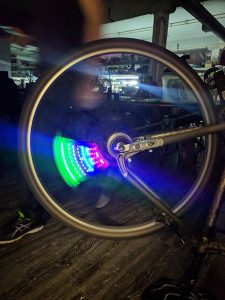
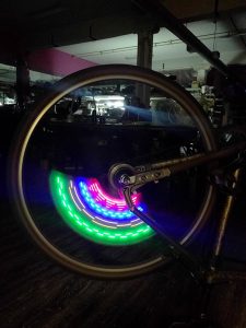
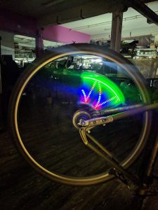
Here are a few terrible pictures of what they look like in action:


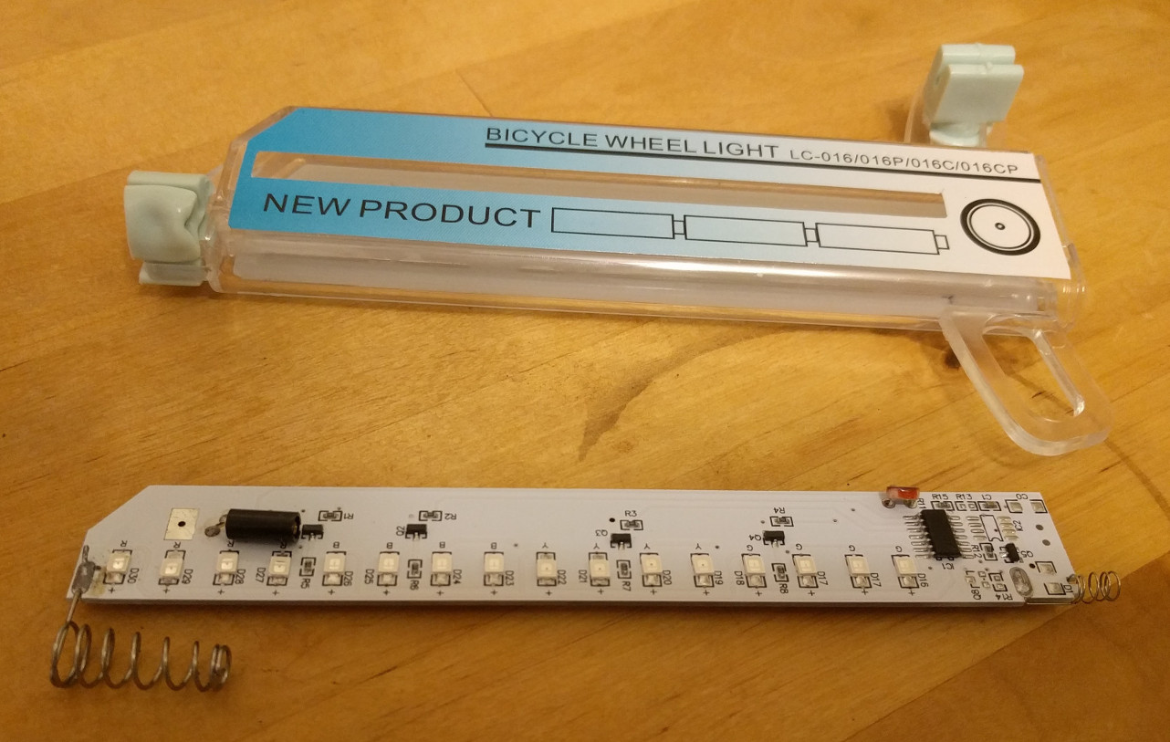
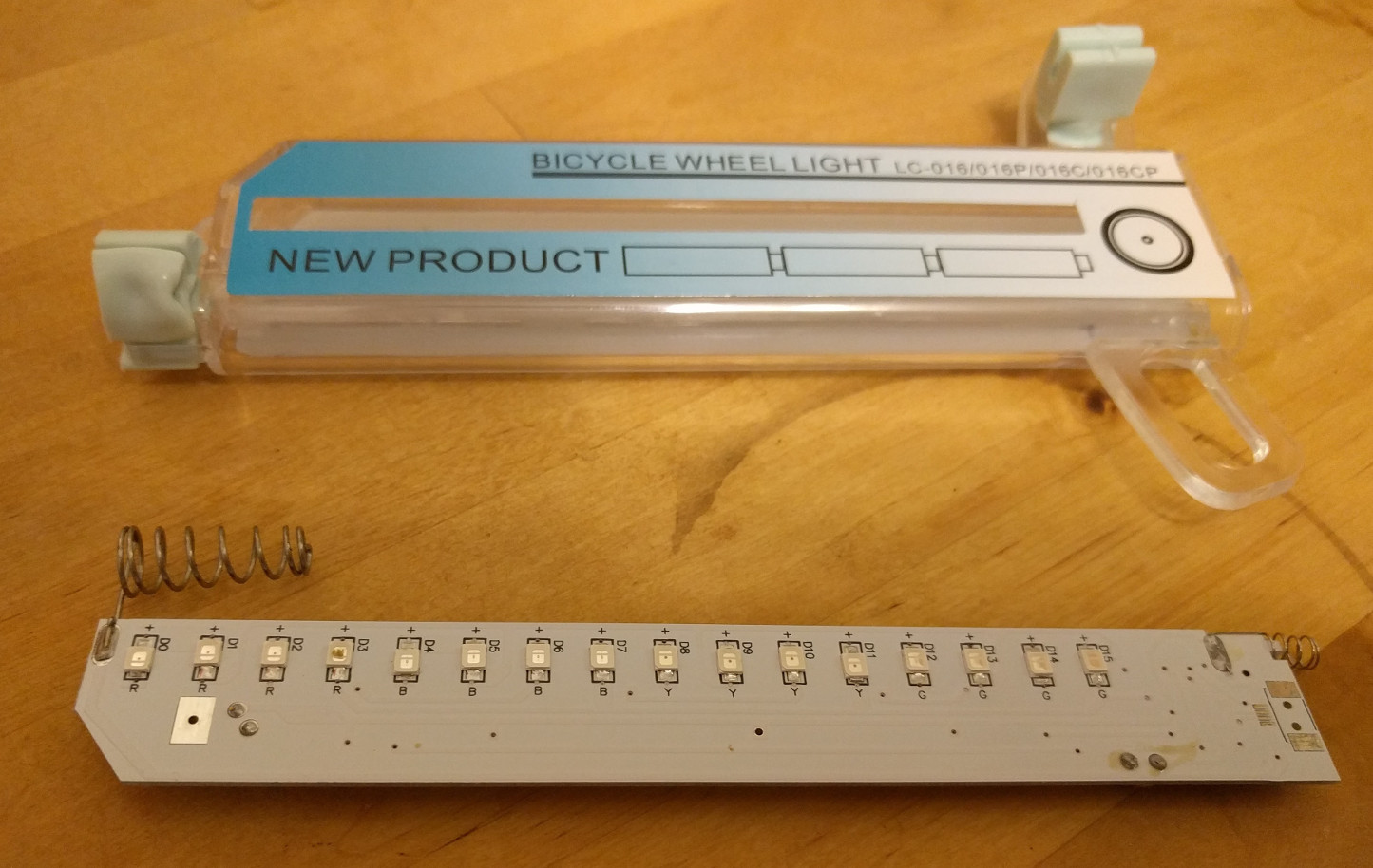
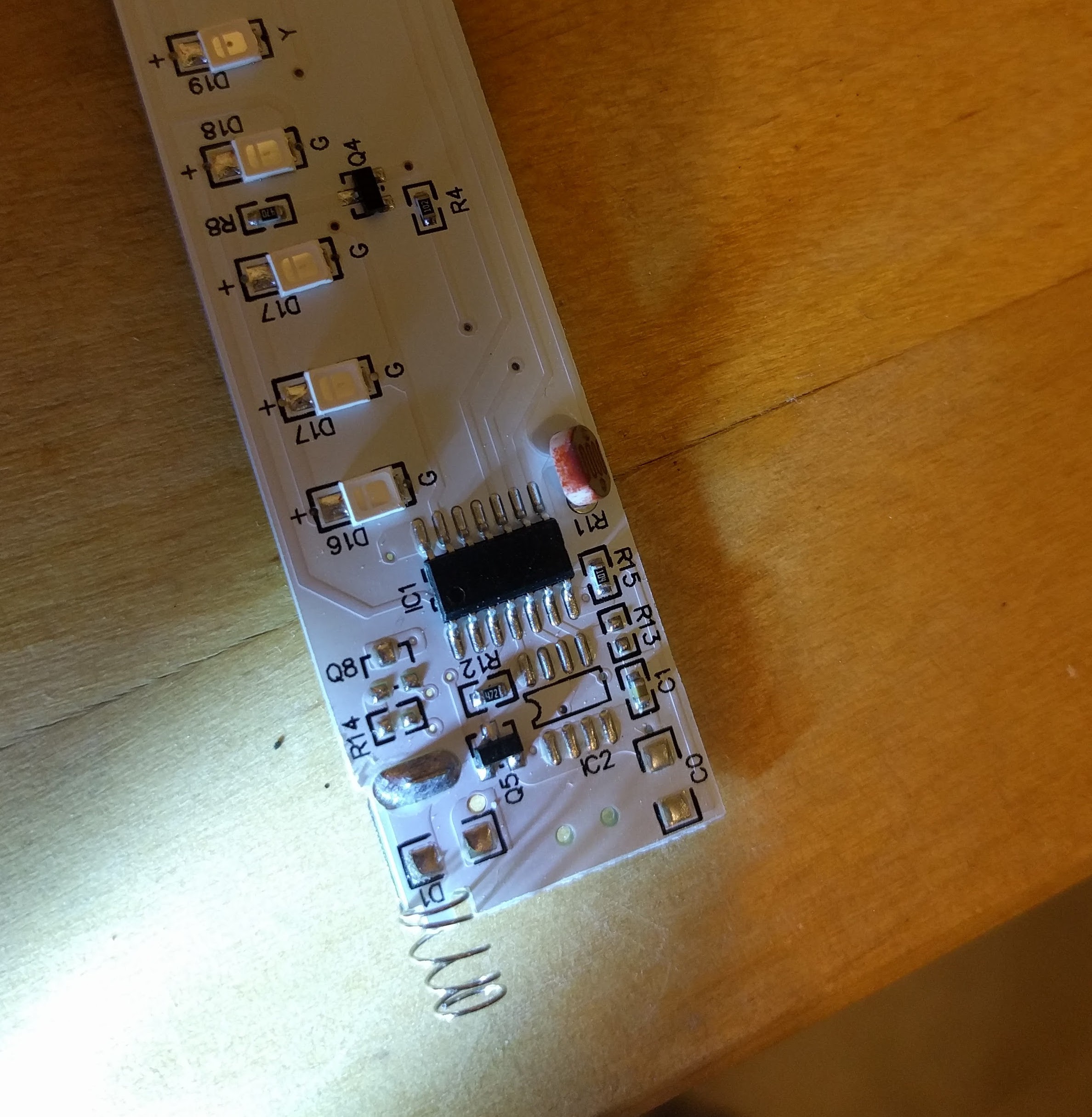
There’s the top and bottom. Fairly straightforward. Light-dependent resistor and vibration sensor feeding into a microcontroller.

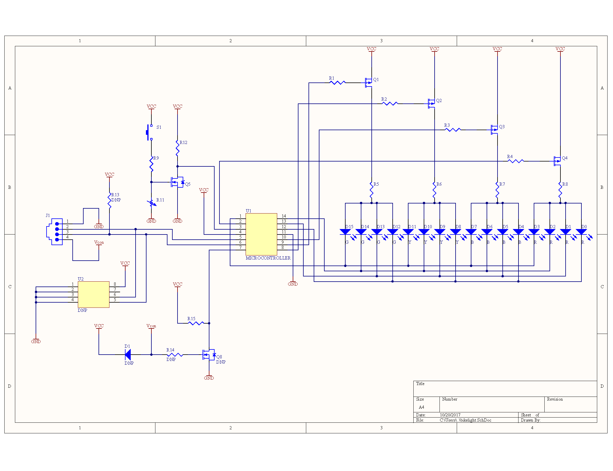
It’s super hard to photograph white soldermask in a way that displays the traces. A combination of that and buzzing pins out results in a schematic, like so:

U2 is probably (similar to) an AT24C02, an EEPROM chip, which isn’t populated in this PCB. Cost reduction on display! There’s an associated pull-up resistor and connector, also missing. Presumably there’s some model out there where you can plug in an I2C device and talk to the microcontroller, or add data to the flash chip.


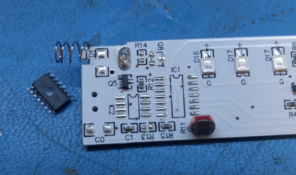
The other one is probably an EM78P153B, based on its pinout. Or very similar. Depending on the exact model, it’s either one-time-programmable memory, or masked ROM from the factory. Either way, there’s nothing I can do to its code. So, removal it is!

It’s interesting to see microcontrollers that rarely come out of China like this.


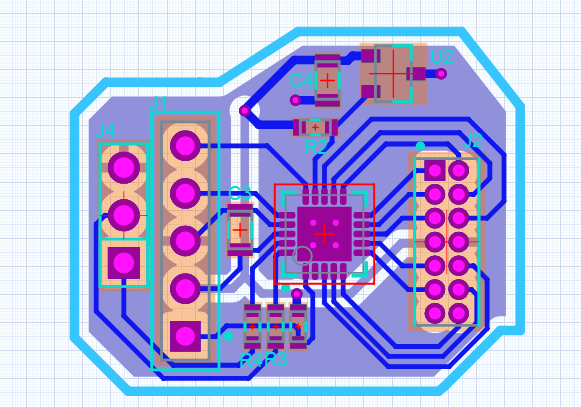
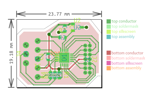
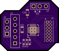
I have a pile of PIC18F14K50, so I threw the footprint onto a small board and headers that matched the 1.27mm pitch of the original microcontroller. I was using Upverter for this PCB, and it provides a pretty neat histogram:


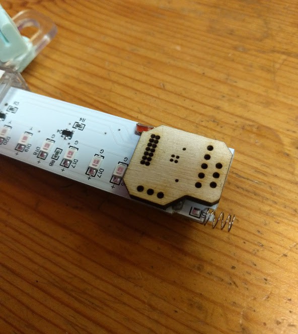
After that, gotta see if it fits, using the convenient laser cutter on hand.


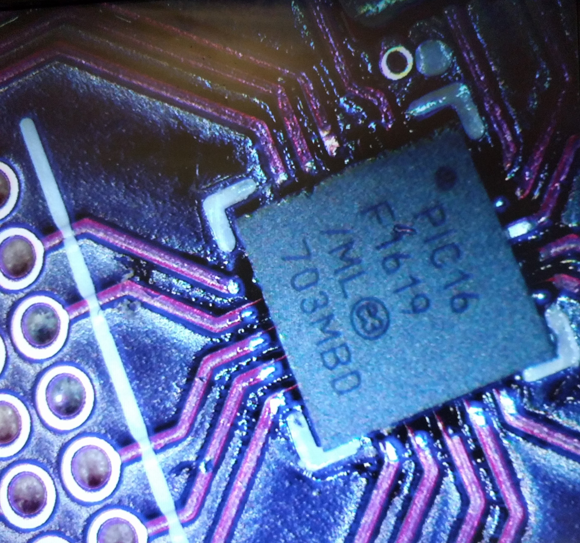
It most certainly does not! So the microcontroller was swapped with a smaller one, the PIC16F1619.


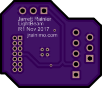
And it totally fits, so off to OSHPark it goes. You’ll notice how neatly the traces were able to be routed on this one. The PIC16F1619 is one of the newer PICs, and they all have something called Peripheral Port Select. Basically, any peripheral can be reconfigured to any pin. It’s pretty fantastic for simplifying board layout.


Receive boards, solder, inspect, looks good!


And then at the same time, remove old microcontroller…


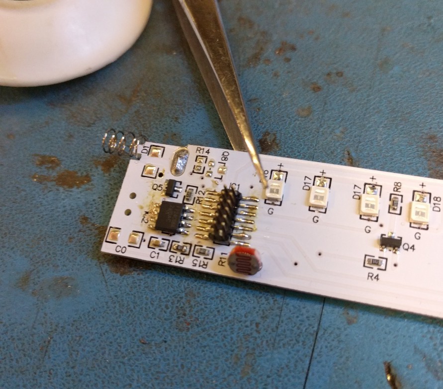
…add new flash chip and headers…

And then solder the whole thing down.


Feel free to fork/download/whatever the hardware files from Upverter, here. I’d be pretty stoked if someone else made some of these, too!

Another hardware update and software is coming in another post very soon. It’s a bit of a tangled web of interrupts, so I’d like to document it properly.

This PCB mostly worked, but the (optional) Hall effect sensor was bad and I changed it. And, final pictures of the result! That’s pretty important.

Clipping the Leads

Here’s a quick one.


I’m tired of having to solder programming headers onto projects that don’t need them after initial development.


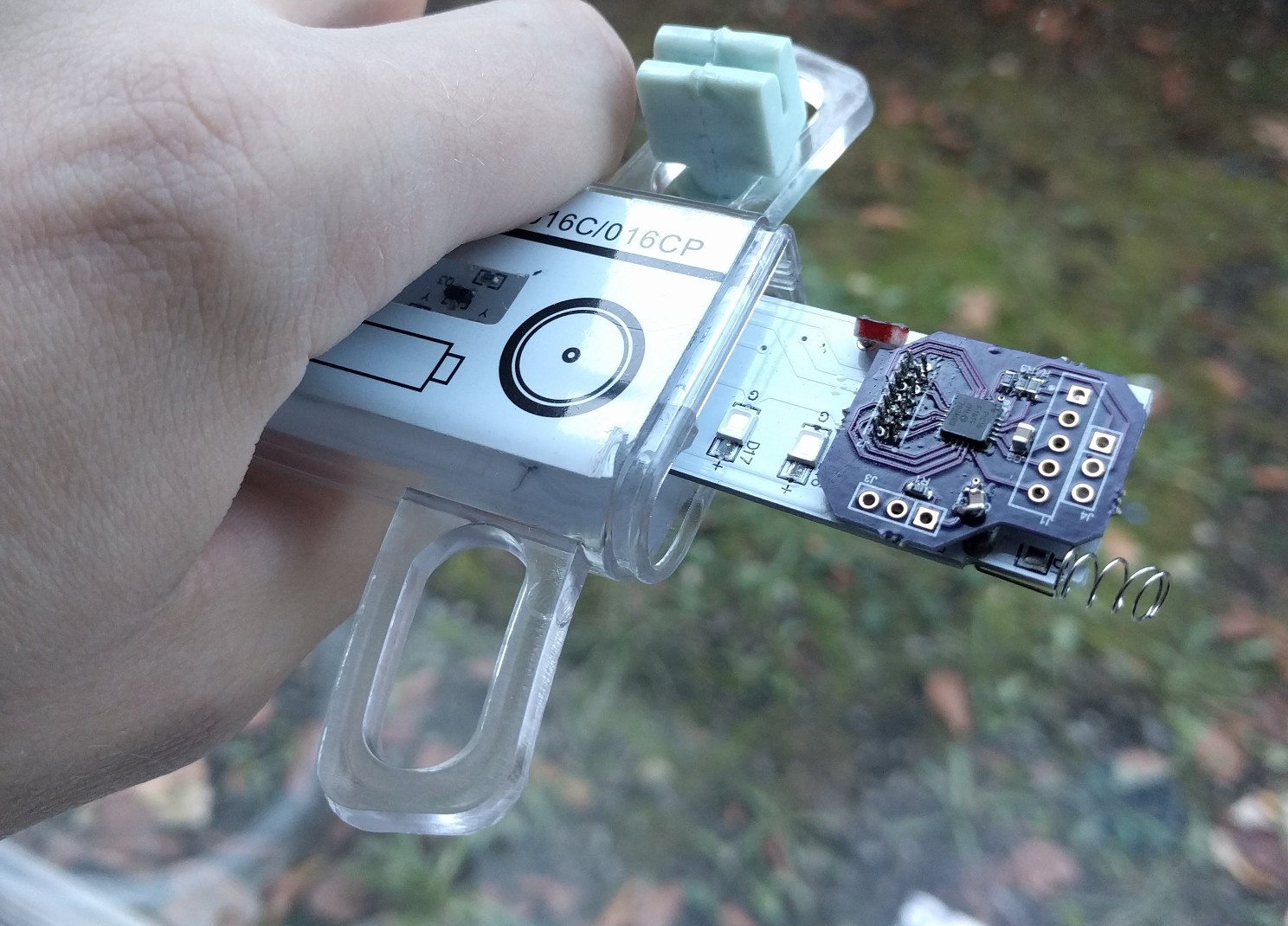
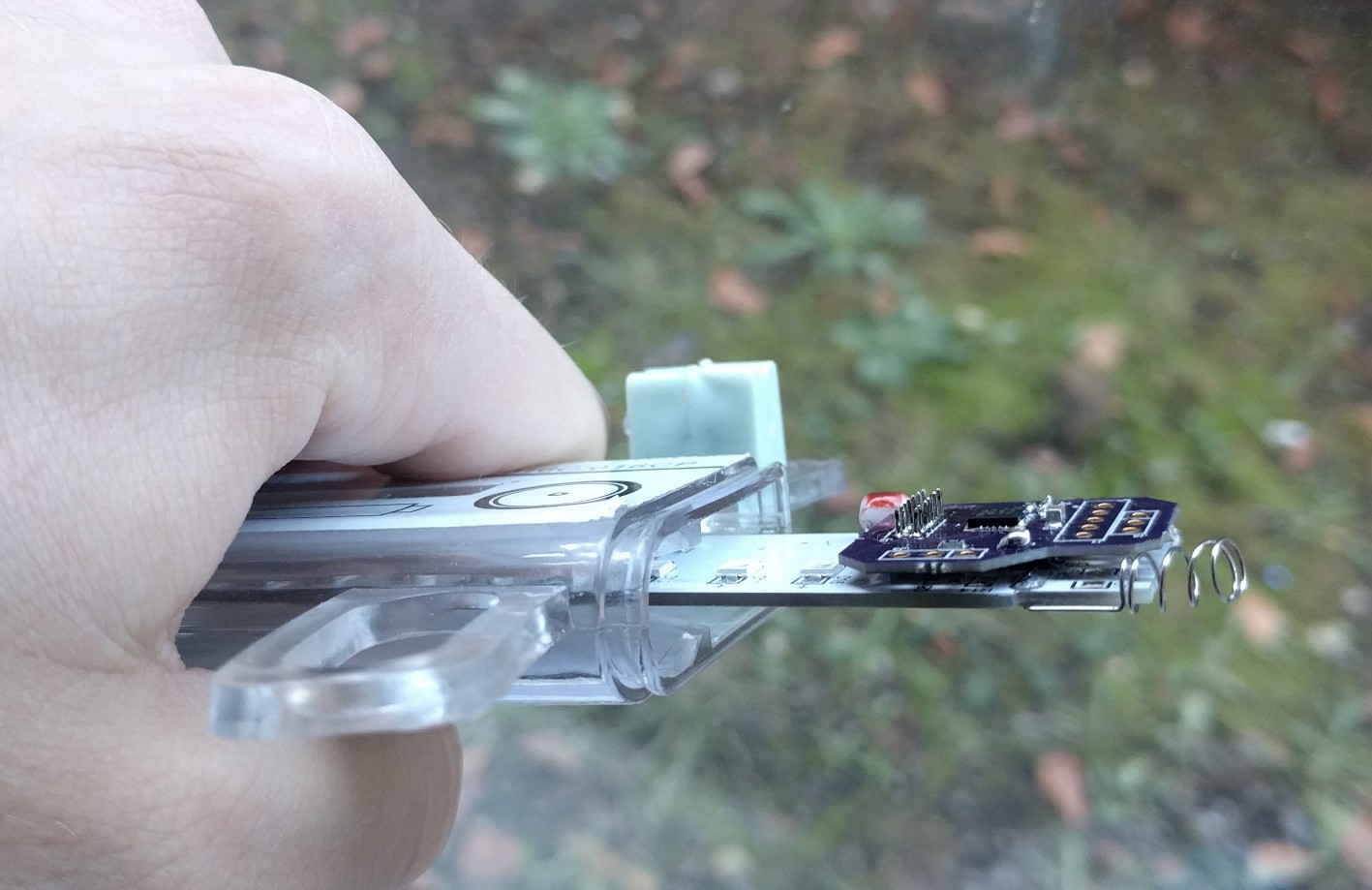
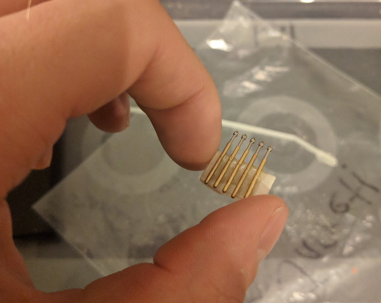
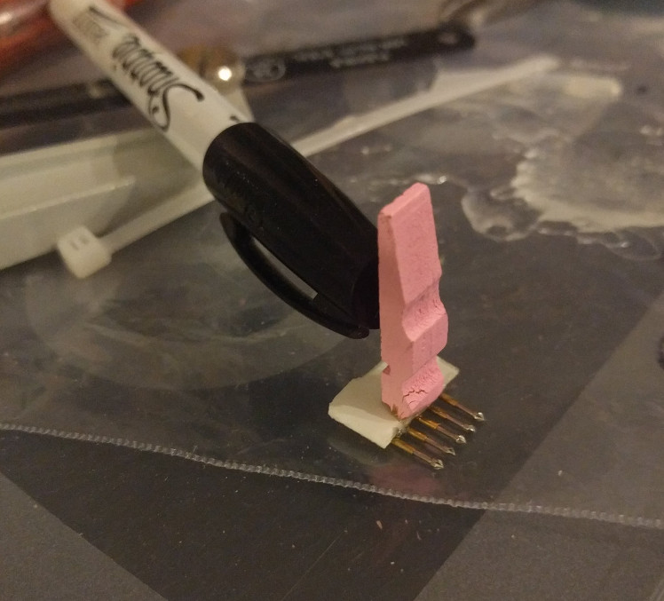
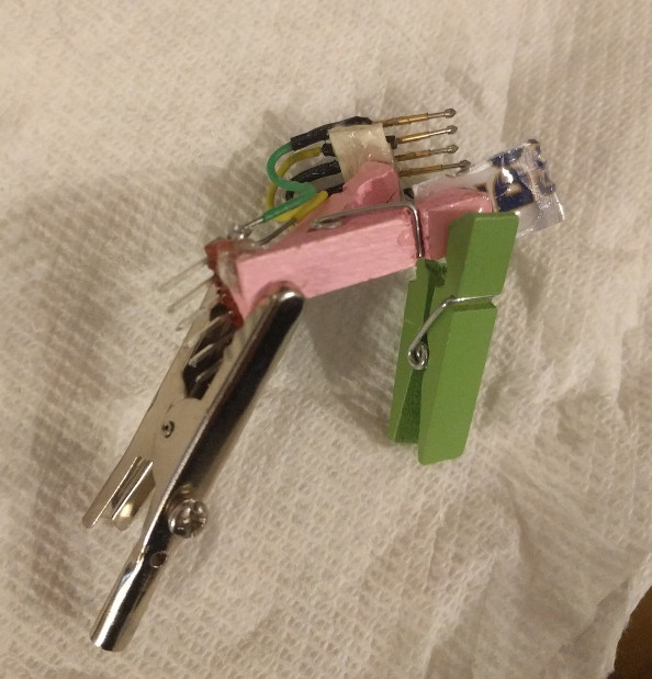
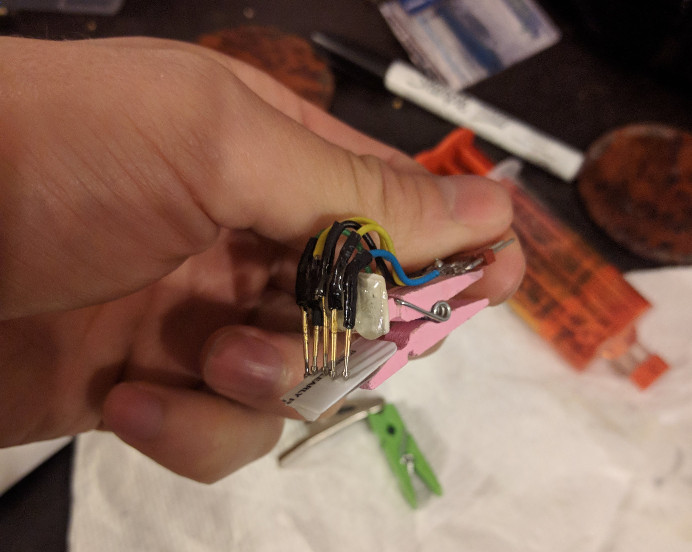
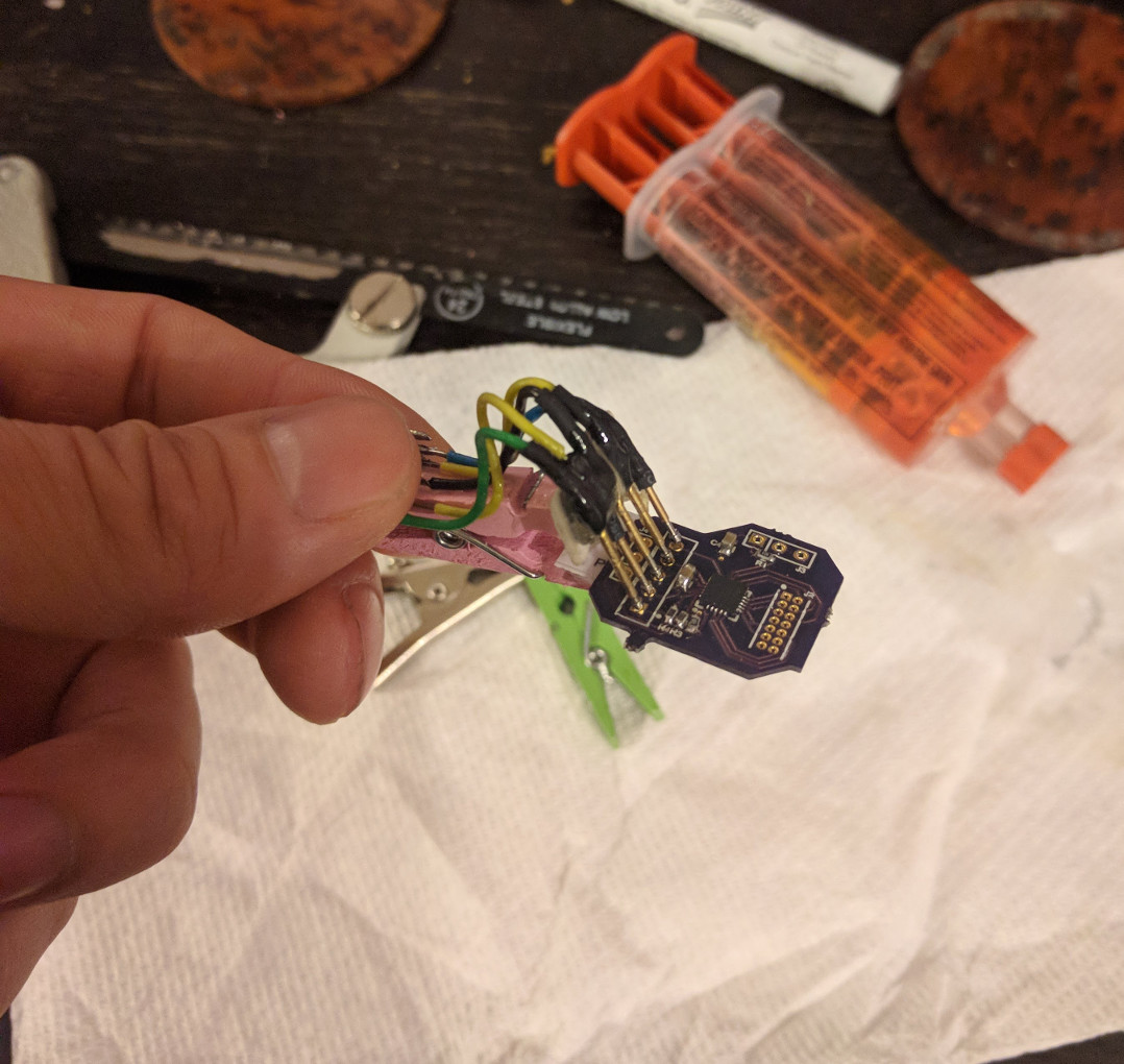
So I bought a bag of clothespins for a couple bucks from China and went wild with some epoxy and Pogo pins.

Soldering made the epoxy fail faster than I expected, so I had to reglue it afterwards.

It works great!

The clothespins are ubiquitous on AliExpress. From the pictures, I expected them to be larger, and plastic. All good, though, these tiny wood ones worked fine.

It’s pretty sturdy on the programming headers. Clips on quickly, and doesn’t need soldering! Success!


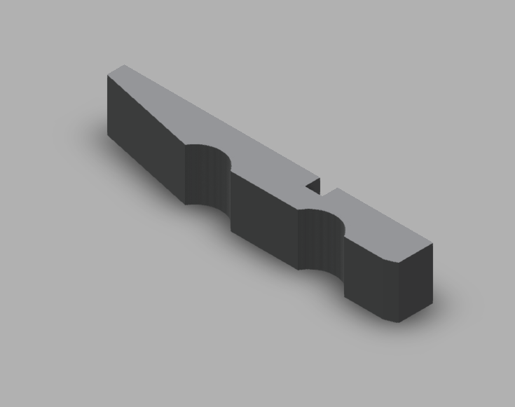
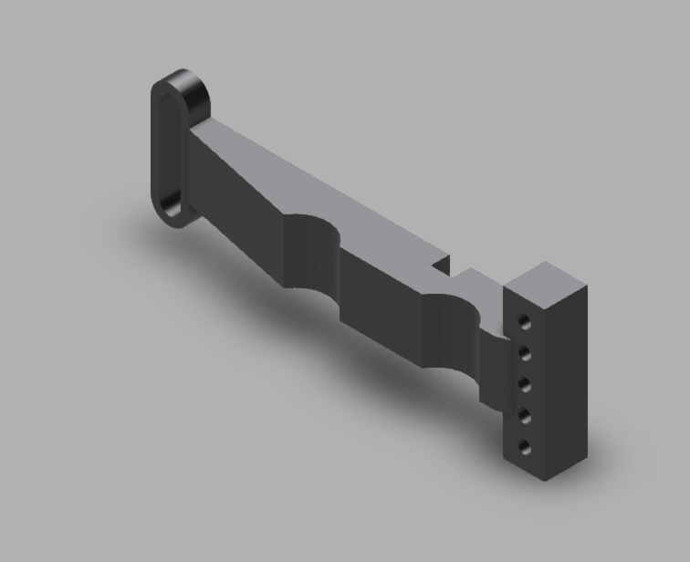
To make this more repeatable and less like an epoxy-globbed-on mess, I took critical dimension measurements and mocked up something in Fusion 360 for future, more polished versions. They should be possible to 3D print, for all occasions.


Here’s the original duplicate half-clothespin, to be modified for any new debug header encountered. A full clothespin consists of two of these, plus a torsion spring. Download here.


Here’s a 5-pin holder, designed for the PIC header format, or any other 5 pin design. Download here.

Next I’ll probably do a 4-pin version for SWD that STM32 (and many other ARM) microcontrollers use. Nothing I have right now regularly requires larger JTAG systems yet, but I’m sure it’ll come. This system should work fine with those, too.

Storytime! A switch mode tale.

A lot of the switch-mode power supplies I’ve built have relied on Skyworks Technologies controllers. This is because they are very cheap, and seem to go obsolete almost immediately after purchase.

This is a quick story of bringing up a new switch-mode circuit from a different manufacturer to test its viability in some battery-powered devices.

I’m using a Richtek RT6150A buck-boost controller.

For a 3.3V output, buck-boost topologies are necessary when the input is a LiPo battery. The ~3.0-4.2V safe voltages for charge and discharge are perfectly bracketing the 3.3V target in a way that is about as inconvenient as possible.


Other than cost, the reason that I selected this chip was that it seemed marketed towards this exact application. Battery technology is written in the advertising materials, and the datasheet shows this:
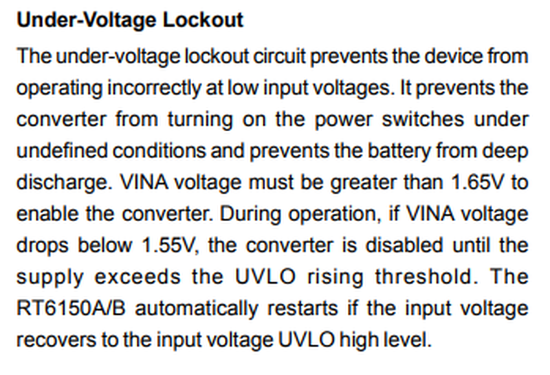
 

Oh yeah,  perfect! An undervoltage cutoff. That should be good for LiPo protection.

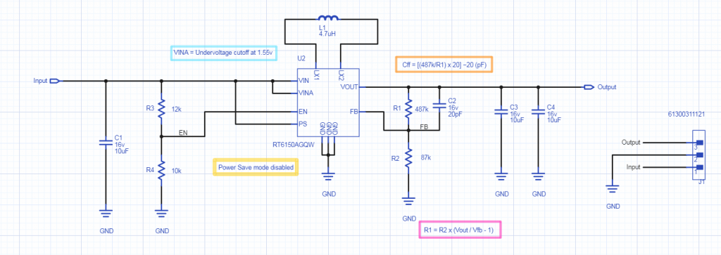
so I drew a schematic like this:
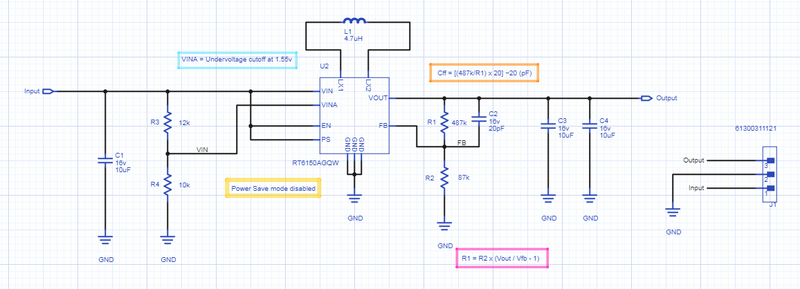
 

And then sent it off as a one-off PCB through OSHPark.

It costed about a dollar.
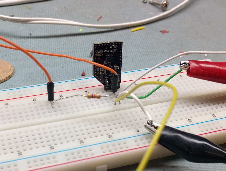


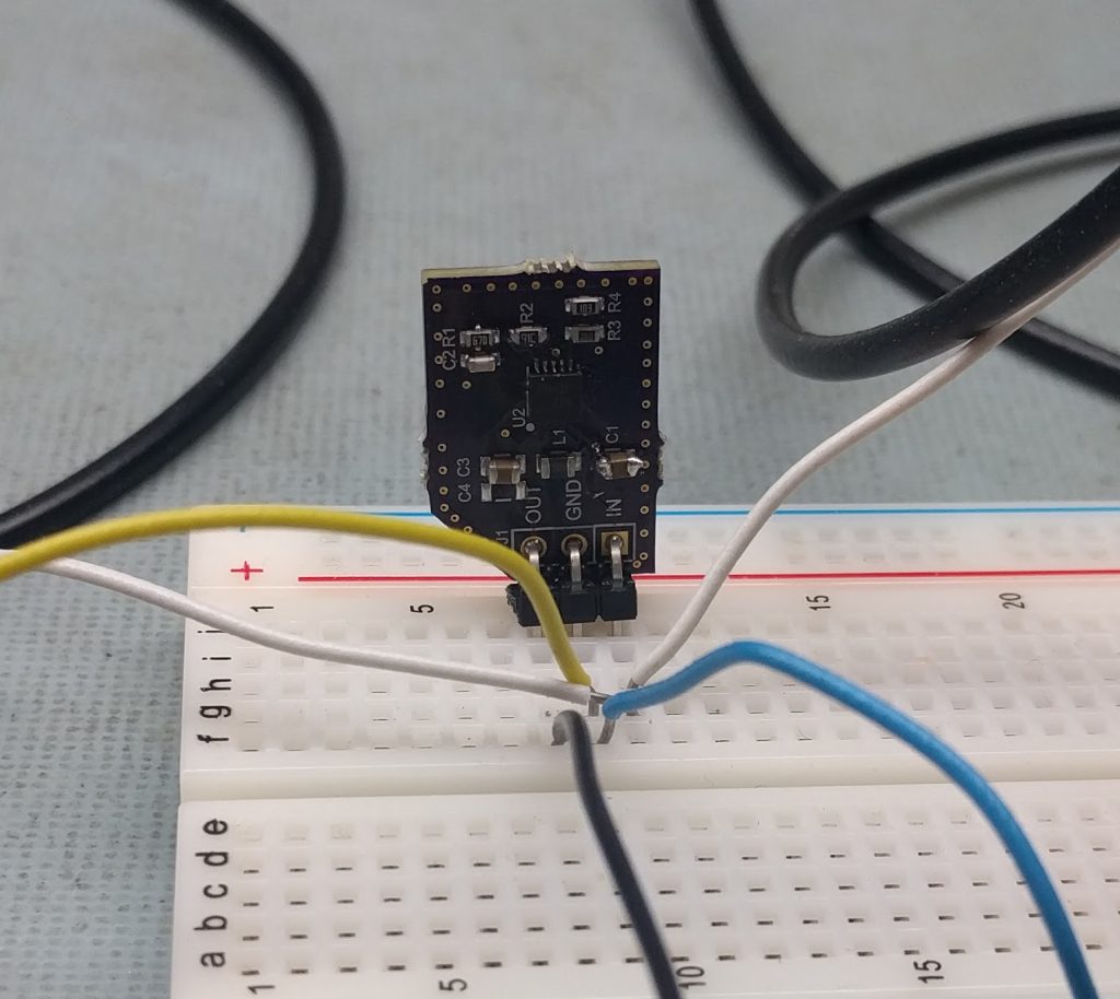
I got it back, soldered it, and did a quick bench-test. Instead of cutting off at 3.3v like I intend, it didn’t turn on until close to 5v.

No good!

So I pulled out the scope and checked the voltage at VINA:
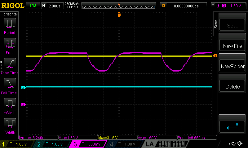


The input voltage was completely stable, so that wavy portion in the middle of the voltage divider wasn’t coming from the input.

Going back to the datasheet:


This was ambiguous, but hindsight tells me it’s not actually intended to be a voltage cutoff. This is just the power for the control circuitry itself.

What was happening was that the internal control circuitry was drawing enough current that the voltage at the middle of the divider sag enough that it hit its cutoff, and turned the chip off, making the voltage rise enough that it turned on again, etc.

This chip is advertised in Richtek’s appnotes as being good for LiPos because of that cutoff, I assumed, but it doesn’t actually work!

So, I bodged VINA to VIN, and now it works, albeit at the full range of the chip. That’s not exactly what I want.

The other thought is to use EN as the cutoff.

It’s supposed to shut the chip off at “logic level low” whatever that means for a wide input voltage chip.


Logic level is anywhere from 1.4 to 1.8v, which is annoyingly wide.


But I gave it a shot.


Some test results:

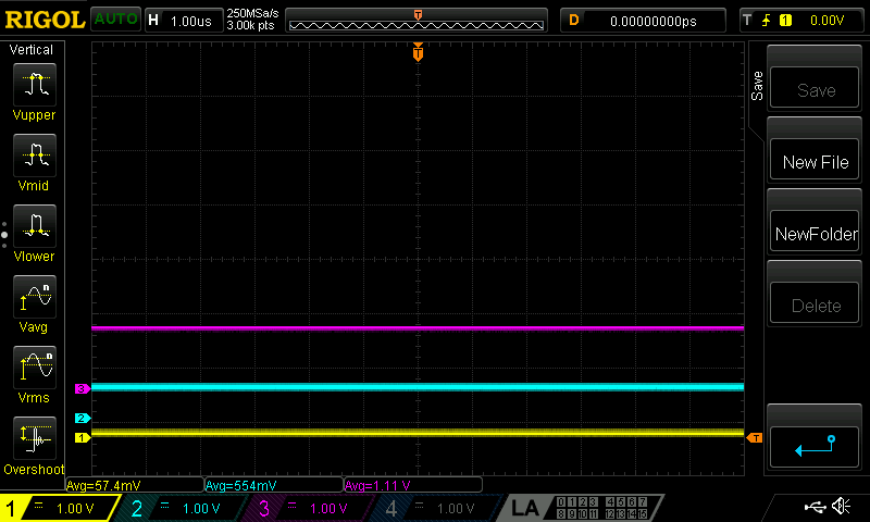
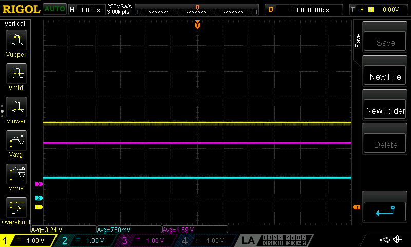
Channel 1(Yellow) is output, 2(Teal) is the EN pin, and 3(Purple) is the input voltage.

At 1.11V input, output is still disabled.
 

At around 1.59V, the output springs up to 3.24V:
 

Weirdly, as the EN pin gets closer to the theoretically 1.55-ish point where it’s supposed to turn on, output noise starts to hugely increase:
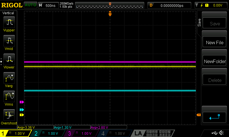
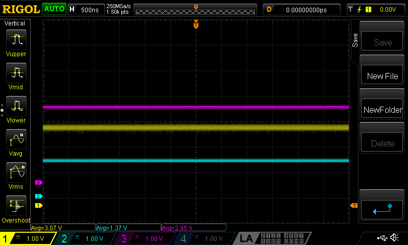
 

Until right at the logic level high point, the output voltage has almost a full volt of non-periodic, constant noise:
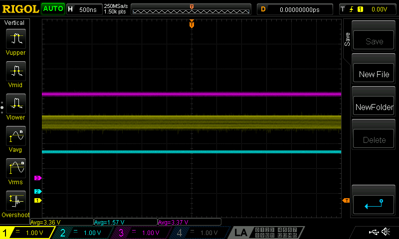
It’s possible that it’s not a coincidence that is right when the controller switches from boost mode to buck mode.

So again, let’s bodge this back into a manufacturer-recommended specification:
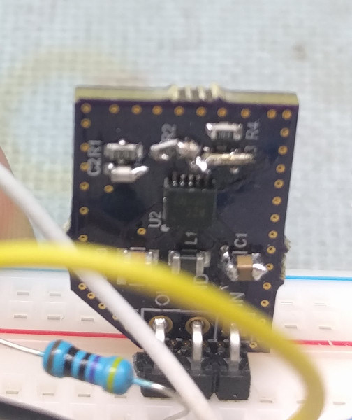
Replacing R3 with a 0-ohm resistor (or: a wire) gets this back into spec:

In this case, the output (teal) is still disabled until the input(yellow) starts to hit 1.50V.
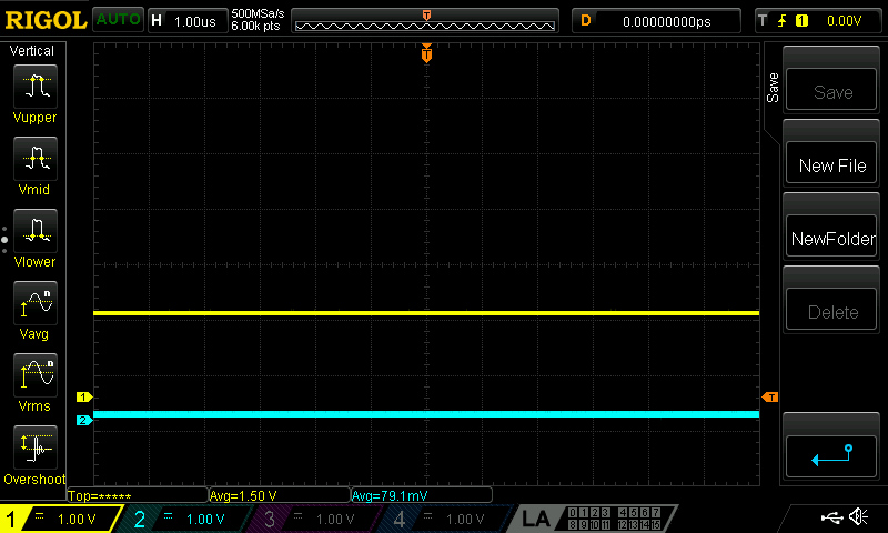
 

From there, there’s a sudden switch-on at 1.56V to 3.2V output:
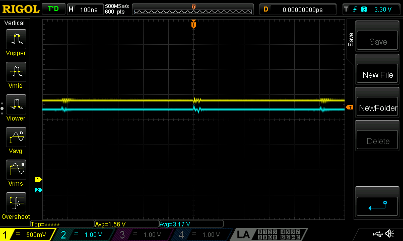
 

And it quickly rises to a 3.3V and stays there for the full range, up to 5V input:
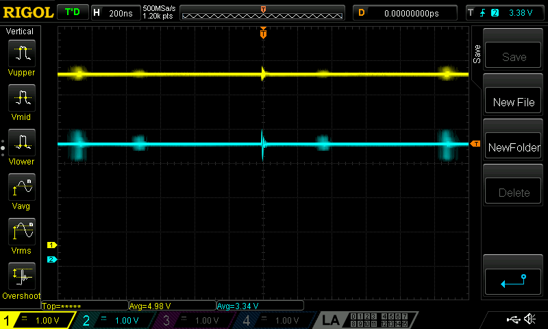
Output ringing is a periodic 1V peak-to-peak for about 20ns, every 1us or so. This gets a little lower when the output is loaded and provides some damping.


So the moral of the story is that the Richtek RT6150A works quite well, but only when the datasheet is closely adhered to. Anything “interesting” in the design leads to unacceptable noise or unpredictable results.


In the meantime, the RT6150A seems to be on the way to phasing out. Stock on Digikey is 0, with a 16 week lead time for new parts. The catalog not-so-subtly hints at using the RT6150B variant, and the datasheet is almost identical. The glaring differences are a few added lines in the marketing copy on the first page saying that fixed 3.3V operation is possible by tying the feedback pin directly to the output.

Anyway, that’s my debugging story. Nothing was particularly novel or unusual, but it was a good process to document irregularities while abusing the chip.
An Extra Special Parcel from China

This is a slightly different post than usual. Typically, I try to only post progress that has already been done, otherwise it ends up as so much vaporware.

For an upcoming project, I wanted to order some parts, write some code, and then use the code to order more parts, but it’s taking a backseat at the moment. So I’ll write about the intended roadmap, instead.


For some backstory:

AliExpress is great. There is a ton of cheap stuff, but it is a littttle bit limited in stock. Popular items only.

Taobao is the answer to that. Chinese language only, but it has everything. Google Translate is your friend. They also don’t ship internationally, but there are reshippers that get around.

Reshippers/fulfillment services are starting to pop up everywhere. I have gone through DirtyPCBs’ service, and the price breakdown is like this:

$item cost + $magic shipping cost + $3 per vendor
+ $15 shipping fee + 15% declared value customs fee


That eats into the savings pretty quickly if you’re buying $2 semiconductors from 5 different vendors. That $2 vendor fee is the largest cost that is avoidable.


The obvious optimisation here is to find all items as you’re trying to purchase, from as few vendors as possible. Many will have a large amount of semiconductors, for example, but no easy way to sift through the matrix of what they’re selling and how it matches up to your shopping cart. That is the basis of what I’d like to do. I’ve written a rudimentary scraper that can grab search results and merchant data, but no overall design of how the interface should look, or how data should be displayed. Future me: probably going to use MechanicalSoup.
 

A good proof-of-concept to try and spur me on to start implementing this came up recently, when I got a generous offer of PCB coupon from Seeed Fusion. I’ve used them before (and bought items from the marketplace, too!), and they’re an awesome company, so it was very appreciated. They do PCBA, stencils, 3D printing, and CNC services too, so they’re positioning themselves as kind of a one-stop shop for prototyping.
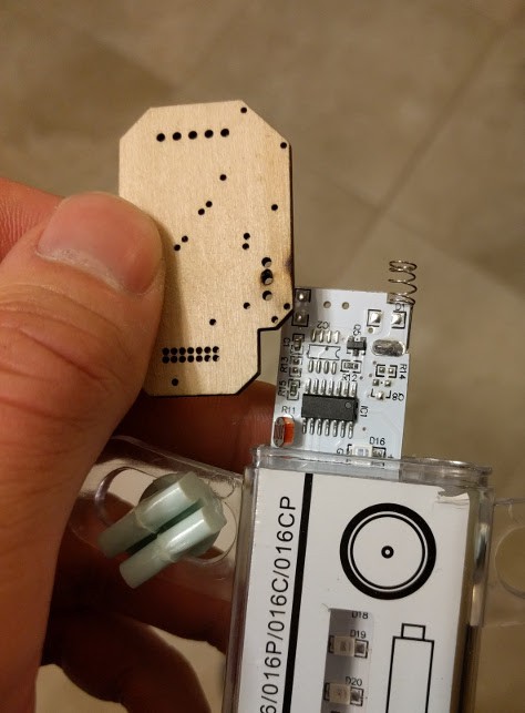
I opted to get a few copies of Benjamin Vedder’s vESC project.

It’s a nice candidate for this because each board requires six expensive MOSFETs(IRFS7530) that cost about $7 each. Taobao lists them at closer to $0.80, although the quality is somewhat suspect.

These boards look fantastic, however:


I opted for yellow, expecting a loud, obnoxious colour, but this turned out to be a very pleasing orangish hue. I may use more of this soldermask colour in the future. Because it’s a 4-layer board, you can see internal layers in the fibreglass that change the look significantly, so I can add three totally different FR4 shades in the “Seeed Fusion yellow” entry in the colour palette I’ve been maintaining.


So this is currently in a mostly-shelved state. When I have a more pressing need for it, I will continue with the Taobao companion application (codename: TaoBeau), and attempt to build out the Seeed board with a $20 BoM cost instead of the Digikey cost of around $90.

Infin1D, Rev 0.5

Before YouTube existed, I saw a video online. There was no spoken dialog, just subtitles in Japanese, with upbeat music in the background. It shows pictures of point-to-point soldering of a document scanner’s sensor and some sort of microcontroller. Then the single line sensor is put into a box (with a lense) and taken for an adventure.

I’d love to find this video again, but the main takeaways were that by reducing your camera to one dimension, you can fake the second dimension to create infinitely long images.

The creator of that original video set it up beside some train tracks, and got a long image of an entire train as it drove past the camera. Similarly, you could put it beside a road and get images of cars, or in the playa at Burning Man and capture the eccentric costumes as Burners ride past on bikes.


I wanted to build a quick test. Lurking in my parts bins, I have a single-line camera module, and a massive pile of old LCDs. For this, I selected an Arduino shield labelled MCUFRIEND 3.6″.

Searching around reveals that this model doesn’t actually seem to exist, but okay! The standard method of most Arduino LCD shield driving is to find example libraries that look like they have a reasonable chance of working, and then try them all until something does. I had to borrow an Arduino, because I’m not a huge fan, so I don’t even own one. How embarrassing.

In this case, the official-looking repository by prenticedavid is here, and GLUE_Demo_400x240 seemed to do a good job of driving this one. The code initialises it as 0x9327, which is the ILI9327 LCD driver. The datasheet for the ILI9327 is very good, so I may keep the LCD and write my own drivers for whatever non-Arduino architecture I eventually go with.

I did attempt to follow the maze of #defines in the Arduino library code, but I don’t recommend anyone do that if they value their sanity. I also put a logic analyser on it to grab just the output; this resulted similarly convoluted and unhelpful results.


While I’ll eventually be using a sensor designed for document scanners (lots more on that, stay tuned), the TSL1401 is a bespoke solution good for this test.


All-in-one sensor, lens, and brains that take logic level timing, and spits out analog values. 127 pixels tall, greyscale, and tiny, it’s objectively kind of bad, but fits the bill for now. I got it up and running in an hour or two.


Cool! That means I have a reference implementation. I’m not running this on an Arduino in the final version, but it got the job done in a quick-and-dirty way.

The whole thing was modeled up in SolidWorks, along with dimensionally accurate stand-ins for the electronics.


There are two 3D printer parts, adapted from the models of earlier jigs I’ve done, in keeping with the ethos of this test: quick and dirty.

I typically design around M3 screws, and used brass heat-set inserts to turn 3D printed cavities into threaded holes. As much as I dislike 3D printing, it has its uses.


Both halves of the 3D printed enclosure failed while doing some of the top few layers, but the baseplates are there so nothing that can’t be fixed with some standoffs and hot glue.


The results from this test project, predictably, are pretty bad.

This is a handheld scan across my keyboard.


As a stepping off point, it’s served its purpose. Here is an incomplete list of changes that future prototypes will feature:

  • A better microcontroller. Probably an STM32F1 or STM32 F4 series. I like the flexible memory controller, which can be used to map virtual memory regions to LCD driver chips.
  • A better sensor. The current one is only 128 pixels tall, greyscale, poor quality, and relatively expensive for what you get.
  • UX – rotary encoders, buttons, LCD widgets:
    • Start/stop capture
    • Speed up/slow down scan/capture rate
    • Integration time adjustment
    • Post capture stretch/compress
    • Histogram
  • Saving to SD card
  • Battery power

Changing the sensor might not actually make it to the next rev, it’s a big project on its own. Sourcing a sensor through Taobao probably, figuring out how it works, driving it, building a board to work with it, and all the mechanical work of lens selection, mounting, and measuring.

Either way, I’m happy to leave this for now, and return to it when I have cleared out some of my project backlog.

Rapidly Building Software to Prototype Quickly


TLDR: I wrote an Inkscape extension to make my life a little bit easier when designing assemblies with laser cutters.


For the most part, I avoid using 3D printers while rapidly prototyping. Until very recently, they have been little better than toys; unreliable, inaccurate, and high maintenance. The laser cutter, however, is a tool. By cutting and joining multiple sheets, three-dimensional objects are still faster and often better than 3D printed parts.

Additionally, when I’m trying to build something really fast, I find it much quicker to sketch out profiles in Inkscape than CAD them up. Inkscape is totally rad open-source vector drawing software, if you’re not familiar. Being able to see assemblies in 3D is nice, but I can do that in my head for quick and dirty projects.

One of the bottlenecks in this process that really messes up my flow is hand-drawing box joints. It’s tedious and error-prone to copy mating profiles that are dimensionally accurate.


But wouldn’t it be great if it only took two seconds?

So this is QuickJoint. It’s a simple Inkscape extension that will add box joints to selected objects.


This first version can do male tabs or female slots. The tabs by selecting a path, and then in the menu choose which side (and direction) to tabify.

The slots will use a single line as a guide, accounting for the laser’s kerf.


This is a work in progress. Fine tuning with how kerf computation works will be tweaked. Slots/tabs may be changed to autodetect so that everything can be done at once. There are a few more changes, for sure.


It’s been tested on Inkscape 0.91 and 0.92, but there was a breaking change in how units are translated in earlier versions, so if you get an error that references self.unittouu, then upgrade your copy of Inkscape! Feel free to submit other issues, with example SVGs.


For a two-minute primer on writing extensions for Inkscape, read on!

Everything is based out of the Inkscape/share/extensions folder.

The recommended method to get started is to find a similar extension to the final project, and use it as a starting point.

Two files are required: A .py and a .inx

The .inx is an Inkscape extension dialog file. There’s a reference here, but for simple stuff, that’s not needed. There are plenty of decent examples in the extensions folder. You’ll start by modifying the dialog options, and then setting the self.OptionParser.add_option of the Python script to match.

For the Python portion, there is a little bit of magic.

Most of the files in the extensions folders are just that: extensions. A few of the files in that folder are special helper files, though. They’re listed here. Inkex has the main Inkscape helper functions, and I used simplepath for SVG writing.

One of the key concepts is that Inkscape mostly gets out of your way while running the Python script. You’re parsing and handling the SVG files directly, with the assistance of those helper scripts. It’s not so bad, SVG is a really simple format – In this case, I only needed commands relating to straight lines, listed full SVG spec.

When Inkscape calls your function, it runs YourExtensionClass.affect(), inherited from the Inkex module, which then calls YourExtensionClass.effect(). Yeah, not a typo. It’s a little bit silly.

From there, the “Live Preview” checkbox in the extension dialog is your friend. The .inx only gets loaded when Inkscape starts, so changes to the dialogs don’t get updated, but the .py gets re-run every time the extension renders.

Sugar Glider Wifi Throwies


I have access to a big box of Nokia phone batteries. This is a problem. It is very large. I do not have enough Nokia phones to use them all.

There are three sizes:

BP-6MT (1050mAh), BL-5J (1320mAh), and BP-4L (1500mAh).

After some catalog-hunting (be vewwy vewwy quiet), I’ve found the connector they use, the A117827CT-ND.


Update: This handy website has sizes of various batteries listed.


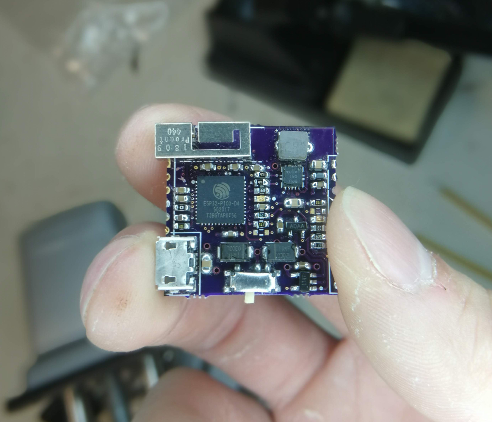
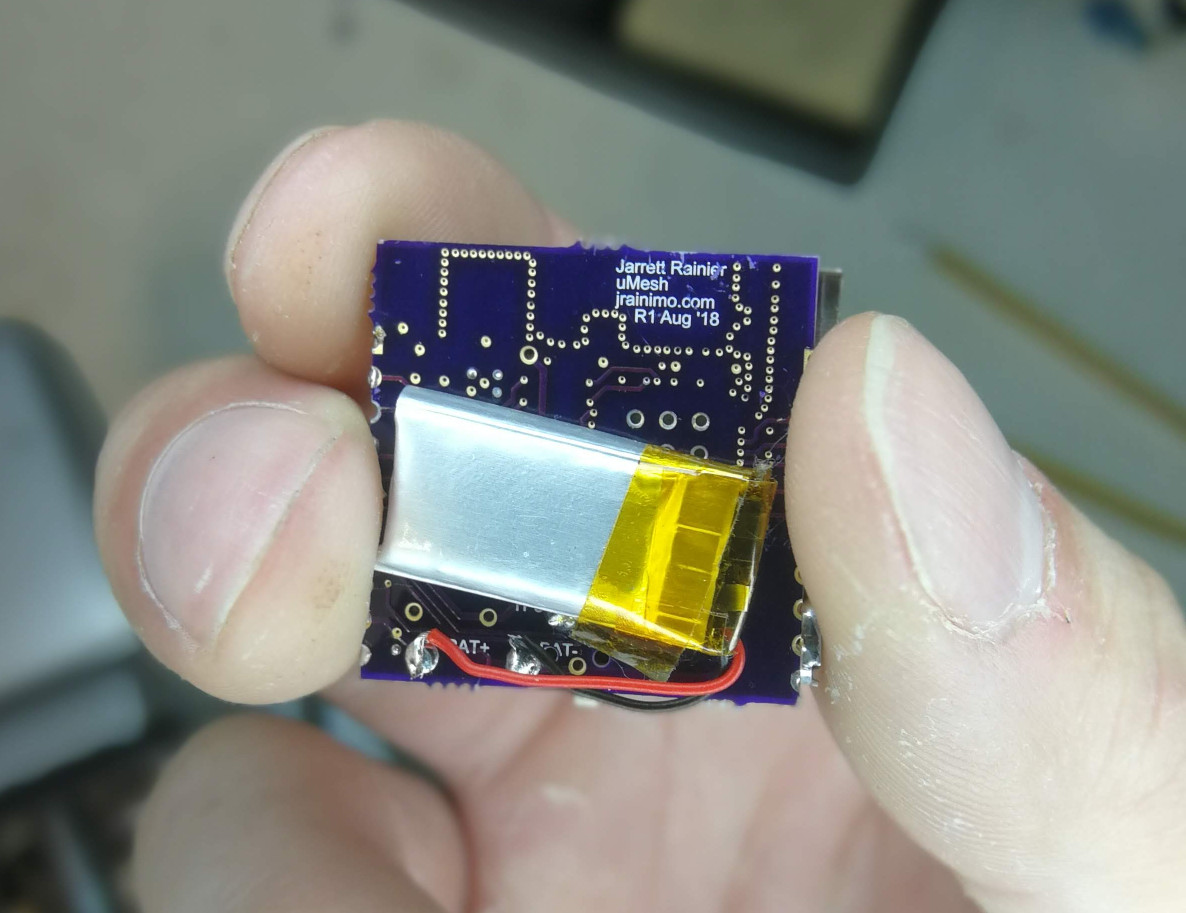
This PCB – I call it “Sugar Glider” – is a battery-powered ESP8266 wifi module. It supports charging a single LiPoly/Li-Ion battery over USB, running off the battery, or both while it’s plugged into your choice of MicroUSB or Mini USB connector.

Mostly using the reference design of the MCP73831 charger chip, and it powers an ESP8266. There is also a CH340G USB-serial chip for programming, so it basically acts like a NodeMCU.


But wait, there’s more! Despite the simplicity of the design, and really not caring that much about it, it took a tonne of time. That’s because I’m rusty at drawing from not having done any in the last decade, and it looks like this!


This was done by exporting gerbers, converting each layer to B&W images, then loading them up in my (also decade old) copy of Photoshop. They were coloured according to my sampled colour palette, and then drawing commenced.

When I was done, they were loaded back into CircuitMaker using the techniques detailed here and here. I think I’ll try to do more of this in the future. Having this much unused PCB space is rare, though – It was needed to act as a sled for the batteries, so it’s quite large. Usually I make boards as small as reasonably possible to save on costs.


The assembly went reasonably smoothly. You have a choice of populating the micro- or mini-USB connections. I prefer the mini, because there are something like 20 different possible microUSB connector footprints. In future versions, I’ll probably also use a 0-ohm resistor to select which one. Having an unpopulated connector on the same line is a recipe for bad signal integrity and unwanted antennas.

The power supply portion of this is simply a low-drop out (LDO) linear regulator, because I wanted to bang this circuit out quickly without having to design a switch-mode power supply (or: the Right way to do this project). Slight problem: the LDOs I sourced from China, well, weren’t very LDO. They had a full volt drop across them, leading to 2.7v seen on the ESP8266 at nominal battery voltage. No bueno.


The solution is very simple; just replace the regulator with a proper part from Digikey, that comes with a datasheet. Modern ones are usually closer to 0.2v. That’s the stuff.

This project was created in CircuitMaker. Here’s a link the cloud project page, but here is a zip file of all the relevant files – Schematics, PCBs, gerbers, and layer drawings. The resource-heavy images don’t play nicely with PCB design, so I recommend deleting them while editing the PCB, and then adding them back in right before export.

Getting Images into CircuitMaker

Jumping off from my last post about getting images into Altium Designer, it was surprisingly difficult to do in CircuitMaker.

After three days of attempting a few different approaches, I have one that I’m quite happy with. Conveniently, this is pretty good at getting images into EAGLE as well. At least as good as the built-in ULP.

If you’re just here for the solution, scroll way down and read the paragraph about the brd-builder.py script.


This is the story of how I arrived at a robust method of importing bitmaps into arbitrary layers in EAGLE cad or Altium CircuitMaker.


The first approach I started with, after drawing some pretty pretty pictures, was to attempt to load them into Altium Designer in the same fashion as described earlier.

These images were way larger and more complicated than the previous experiment, however, and the Delphiscript chewed on it for three or four hours before silently failing. Even if it had worked properly, I’m not particularly happy about being dependent on the expensive professional tool to work with the hobbyist one. So I delved deeper.

Here are the options and approaches I took:

  • Importing DXF files directly in Circuitmaker is possible, but largely unsatisfying. The CM importer splits up the original paths into discrete arc and line segments. This is great if you want to draw outlines, but that’s it. Lack of fill options or the ability to merge these objects make it inadequate for my purposes.


  • Using CircuitMaker “region” objects. Going into the property menus of one of these objects reveals a list of points and coordinates, and import/export options. I wrote a converter to massage SVG files into the proper CSV format. This is svg-parse.py. It’ll take an SVG file, and convert each individual object into a CircuitMaker-compatible CSV file. From there, you can create a region in CircuitMaker, open its properties, and import one of the CSV files.

This is pretty good, and results in native objects that are speedy to move around. There are some caveats, however:

  • You must do this for each object, making it labour-intensive for complex canvases
  • Curves are not supported, so it is first necessary to follow the “Add Nodes” and “Flatten Beziers” steps in Inkscape, described in the import-dxf EAGLE plugin.


  • Attempting to hijack the clipboard was the next experiment, read-clipboard.py. Region objects can be copy-and-pasted between documents, so I wanted to take a look at what that data contained, and maybe silently insert my own. This never really worked properly, and I abandoned it quite quickly. It was a hacky approach, anyway.


  • A quick search on reverse-engineering Altium’s file format brought up this primer (by way of Hack-A-Day). Although very abbreviated (the goal of that guide is to teach a methodology, not to completely reverse the file format), the page was more than enough information for me to write a Python script that opens and dumps the contents of the CircuitMaker-formatted OLE document. So in ole-extract.py, I got as far as grabbing a library document and extracting and splitting header/data information into a folder. Realised at this point that the libraries I was using would have a difficult time repacking the streams into one OLE document. Not to say it isn’t possible – it totally is – it’s just rabbit-hole I don’t particularly want to go down at this time. This is still interesting in that it should be a working Altium and CircuitMaker file reverse engineering effort in Python, which hasn’t been done before.


  • Importing EAGLE files works really well. They’re XML-based, and very well documented. First, I imported an EAGLE file that contained an image, which looked and worked great in CircuitMaker. I poked around with how that image was created in EAGLE, and it looks like it was just made with the built-in “Import Bitmap” ULP. How it works is that it scans along each horizontal line, creating a one-pixel-high rectangle in the filled area. Repeat for the entire image.

Okay cool. That sounds really simple. Problems with that:

  • It doesn’t alleviate my allergy to using 3rd-party software as an intermediate step
  • If my image is over the 3 inch (or whatever) size limits of EAGLE’s free version, I’m hooped
  • The ULP script seems to choke on images randomly

So what I did instead, is take a dummy EAGLE file, and stripped it to the bare-necessities required to load. This particular brand of XML is the fourth file format I’ve had to parse in this whole process, but it wasn’t too hard. With this dummy file, my final and greatest script, brd-builder.py, grabs a bitmap file, converts and then injects it directly into the EAGLE file, giving you a proper EAGLE file, with no size limitations and no EAGLE install required. CircuitMaker can then easily import this via the File->Import menu.

Input images need to be a 1-bit BMP file.  In Photoshop this is done by converting to grayscale in Image->Mode->Greyscale and then converting to bitmap in Image->Mode->Bitmap. In GIMP, this is done through the menu in Image->Mode->Indexed. Then save as BMP.

Before running this script, open it up and then modify the desired variables – inFile, outFile, layer, and scale. They should be fairly self-explanatory. Scale in my application was found by guessing until it fit my board, due to the resolution I drew my image at.


This was a fun detour. Fun is good, because spending time to make tools for your tools can be very frustrating. The last tool in particular works great for me, but If I were to develop a robust system designed for anyone to use, there are a few more avenues I would attempt to pursue first:

  • In the Hack-A-Day link posted above, one of the comments mention being able to just open OLE. They turned out to be using 7zip, which supports that format natively. Coincidentally, I found a portable 7zip executable in the CircuitMaker folder. It’s possible that they’re using this for encoding their documents. It would be fun to write an executable shim with the same filename that invisibly passes arguments to the original 7zip program, but logs it to file as well. Will also look into better methods for doing this – Static analysis using X64_DBG or IDA is an obvious candidate here.


  • Failing that, writing and testing code to modify the OLE document stream and then repack it into a format that CircuitMaker can read


  • The native importers in the CircuitMaker all have IWZ extensions, and from the binary data seem to be x86/64 executables. Google says these might be installer files. Along the same lines as the executable shim/wrapper above, figuring out how these work and writing my own would be fun.